Ariens sno-tek 920401 User Manual
Page 25
GB - 25
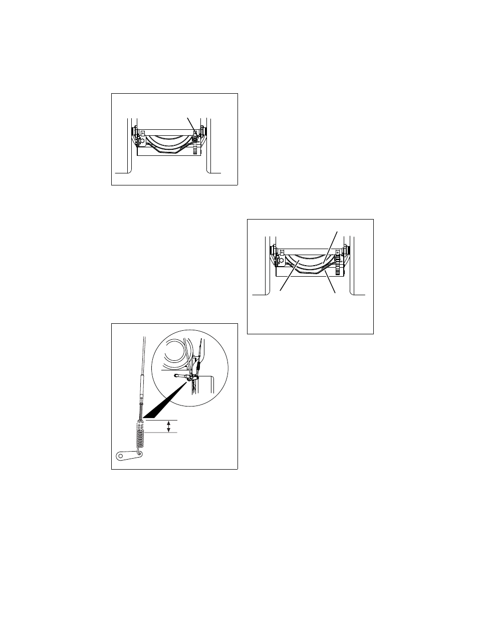
Adjust the Attachment Clutch Cable
Spring Extension
(Figure 26)
1. Check the attachment clutch cable
spring extension.
Measure the length of the attachment
clutch cable spring with the clutch lever
disengaged.
Then measure the attachment clutch
spring with the clutch lever engaged.
The spring should be 1/2 – 9/16 in. (12.7
– 14.3 mm) longer when the clutch lever
is engaged.
•
If spring extension is within the
specified range, go to Check
Attachment Brake on page 25.
•
If spring extension is outside of
specified range, go to step 2.
2. Adjust cable length (Figure 26).
a. Loosen jam nut on cable.
b. To increase spring extension,
adjust barrel down the cable and
tighten jam nut.
c. To decrease spring extension,
adjust barrel up the cable and
tighten jam nut.
Check Attachment Brake
(Figure 27)
1. With the clutch lever disengaged, brake
pad must contact attachment belt. With
clutch lever engaged, brake pad must be
more than 1/16 in. (1.6 mm) from belt. If
there is more than 1/16 in. (1.6 mm) gap,
go to Check Belt Finger Clearance on
page 26. If there is less than 1/16 in. (1.6
mm) gap, go to Step 2.
2. If there is less than 1/16 in. (1.6 mm)
gap between brake pad and belt, follow
these steps:
a. To increase brake pad gap,
loosen idler adjustment nut, and
move idler away from belt.
Position idler to achieve a 1/16 in.
(1.6 mm) minimum brake pad
gap and a 1/2 – 7/8 in. (12.7 –
22.2 mm) gap between the
plastic roller and the frame.
b. Check the clutch cable spring
extension and adjust as
necessary to achieve a 1/2 –
9/16 in. (12.7 – 14.3 mm) spring
extension.
c. If the cable needed adjustment,
recheck gaps described in step 1.
Repeat steps as necessary until
brake clearance, roller gap and
spring extension are within
specified ranges.
IMPORTANT:
If adjustments cannot be
brought into specified ranges see your dealer
for repairs.
Figure 25
OS8080
Roller should be 1/2 – 7/8 in. (12.7 –
22.2 mm) from the frame when the
attachment clutch is engaged.
Figure 26
OS8085
1/2 – 9/16 in.
(12.7 – 14.3 mm)
Figure 27
OS8092
Minimum of 1/16 in. (1.6 mm)
1. Brake Arm and Pad
2. Attachment Pulley