Names of parts and functions, Precautions, Specifications – Sony PCWA-DE50 User Manual
Page 2
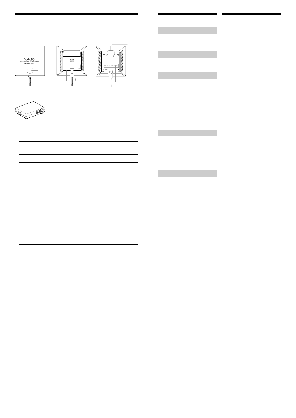
Names of parts and functions
Wireless Unit
Front panel
Rear panel
(With rear panel removed)
1
3
2
4 5
7
6
Power Unit
8
0
9
1
STATUS indicator
Shows the operation status of the Wireless LAN Converter.
Indicator color and lighting pattern
Status
White flashing (approx. 9 sec. lit, 1 sec. out)
Wireless network connection status:
Good (strong signal)
White flashing (approx. 5 sec. lit, 1 sec. out)
Wireless network connection status:
Fair (medium signal)
White flashing (approx. 2 sec. lit, 1 sec. out)
Wireless network connection status:
Poor (weak signal)
White flashing (approx. 1 sec. lit, 9 sec. out)
Nothing connected to the NETWORK connector or
connected devices off.
White flashing (approx. 0.4 sec. intervals)
Startup in progress
Wait until startup is completed.
Pink lit
Communicating in Peer to Peer Network connection
mode
Red flashing (approx. 3 sec. intervals)
Search for wireless network in progress
Communication is not yet possible because connection
is not established. If this condition continues for a long
time, check the settings of the Wireless LAN
Converter and the connection target (5GHz Wireless
LAN Access Point, etc.).
Red flashing (approx. 0.4 sec. intervals)
• Unit is ready for reset
Reset switch is being pressed and unit is now ready
for reset. Release reset switch. Wireless LAN
Converter restarts automatically, and all settings
revert to factory defaults.
• Firmware update in progress
Firmware is being updated. Never turn power off in
this condition.
2
Reset switch
Serves to return the Wireless LAN Converter to the factory default condition. For details, refer to the
separate Quick Start Guide or Online Help.
3
LINK/ACT indicator
Lights up when a link has been established through the NETWORK connector 0. While data are being
exchanged, the indicator flashes.
4
Wireless Unit cable
Connect to the Wireless Unit connector 9 on the Power Unit.
5
Rear cover
Remove this cover when wishing to mount the Wireless Unit on a wall, and when wishing to check the
MAC address of the Wireless LAN Converter.
6
Wall mounting holes
Used for mounting the Wireless Unit on a wall. For details, refer to the separate Quick Start Guide.
7
MAC address label
This label shows the MAC (Media Access Control) address of the Wireless LAN Converter.
z
Hint
MAC address is a unique identifier assigned to each Ethernet-compatible device. Because a different MAC
address is specified for each device, no two devices have the same MAC address. Further, users cannot change
MAC addresses.
8
AC 100-240 jack
Connect the power cord here.
9
Wireless Unit connector
The Wireless Unit cable 4 is to be connected here.
0
NETWORK connector
Use an Ethernet cable to link this connector to a computer or another device with an Ethernet connector.
z
Hint
You can use an Ethernet cable with straight-through or crossover wiring.
Precautions
Power Unit
Use only the supplied Power Unit and power cord.
Other AC adapters may damage in the Wireless
LAN Converter.
Safety
Do not drop the Wireless LAN Converter. Careful
handling will help prevent damage.
Installation
Do not place the Wireless LAN Converter where it
will be exposed to the following conditions:
•
Unstable surfaces.
•
High humidity or poor ventilation.
•
Excessive dust.
•
Direct sunlight or extreme heat.
•
Closed cars.
•
Magnetic fields (near magnets, speakers, or
televisions).
•
Frequent vibration.
•
Locations where the transmission of radio
waves may be obstructed by metal plates or
concrete walls.
Operation
Exposure to rapid changes in temperature or very
damp environments may cause moisture to
condense on internal parts. This may prevent the
Wireless LAN Converter from operating properly.
If this should happen, unplug the Power Unit from
the power outlet and allow the Wireless LAN
Converter to dry for two to three hours or until the
moisture evaporates.
Cleaning
Clean the casing with a soft cloth lightly moistened
with water or a mild detergent solution. Do not use
any type of abrasive pad, scouring powder, or
solvent such as alcohol or benzene. This may
damage the finish of the casing.
Specifications
Power
AC100 - 240 V, 50/60 Hz
(The power cord plug is for use with AC 120 V.)
Power consumption
Approx. 5 W
Interface
100BASE-TX/10BASE-T (RJ-45) (automatic
MDI/MDI-X detection)
Maximum external dimensions
Wireless Unit: approx. 3.9
Ч
3.9
Ч
1.3 inches (w/h/d)
(approx. 98
Ч
98
Ч
33 mm)
Power Unit:
approx. 4.4
Ч
1.0
Ч
2.8 inches (w/h/d)
(approx. 110
Ч
25
Ч
70 mm )
Mass
Wireless Unit: approx. 11 oz. (approx. 310 g)
(incl. connection cable)
Power Unit:
approx. 4.6 oz. (approx. 130 g)
Maximum connection distance
Line of sight approx. 328 feet (100 m)
(The maximum connection distance depends on the
environment.)
Protocol support
TCP/IP
Standard
IEEE 802.11a (wireless connection)
IEEE 802.3 (wired connection)
Radio frequency
5.15 - 5.35 GHz
WEP (Data encryption)
64 bits/128 bits
Modulation method
OFDM (IEEE 802.11a compliant)
Operating temperature
41°F to 95°F (5°C to 35°C) (no condensation)
Storage temperature
–4°F to 140°F (–20°C to 60°C) (no condensation)
Supplied accessories
• Wireless Unit
• Power Unit
• Power cord
• CD-ROM (Setup disc)
• Read This First (this manual)
• Quick Start Guide
• Troubleshooting Guide
• Limited Warranty
Design and specifications are subject to change
without notice.