Haltech Platinum PRO PLUG-IN Nissan Patrol Y61 2002 - 2009 (HT055014) User Manual
Page 7
Rear Auxiliary Connector
The Platinum Pro Plugin Series allows further expansion of your ECU by the
Rear Auxiliary Connector.
The Rear Auxiliary connector allows you access to:
•
2 Additional Digital Pulsed Outputs ( DPO )
•
2 Additional Digital Switched Outputs ( DSO )
•
2 Additional Analogue Voltage Inputs ( AVI )
•
2 Additional Analogue Temperature Inputs ( ATI )
These extra Inputs / Outputs can be used to:
•
Fit additional sensors. (eg MAP and Temperature)
•
Control additional devices via relays
•
Control additional solenoids directly (eg Aftermarket Boost Control solenoid)
The Rear Auxiliary harness is available as an optional extra. ( HT040003 )
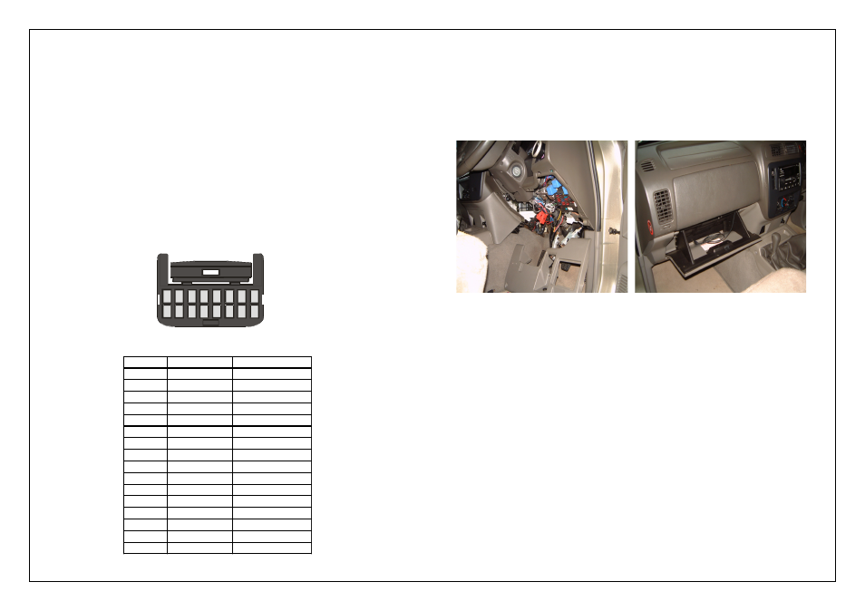
Figure 9 - Rear Auxiliary Harness Connector and Pinout
6.
Re-fit the Haltech ECU to the vehicle making sure that you connect the
MAP hose, auxiliary plug (if used) and the USB Cable before mounting it
to the vehicle.
The USB cable can be routed behind the center console and left in the glove
compartment for tuning
Secure any cables away from any moving parts under the dash with cable ties
Re-fit the lower dash panel to the vehicle.
Figure 7
Figure 8
Haltech ECU Mounted in Vehicle USB Cable in glove compartment
7.
With the Haltech ECU installed do not attempt to start the vehicle. You will need to
configure the ECU. The Haltech ECU is pre-configured for use with a TB48DE
standard engine. If this is your setup then you will not have to load a basemap.
If your engine is not standard please adjust any configuration setting affected according
to your setup. You may need adjust your maps, or load a map to suit your modified
engine before it will start.
With the suitable settings and basemaps loaded, your engine will now be able to be
started.
8.
With the engine started and running it's now time to tune
This is best achieved by your nearest engine tuner
See the listing of Haltech dealers on our website to find the one closest to you
Pin #
Wire Colour
Connection
1
O
+5V
2
Y
AVI1 (MAP)
3
O/B
AVI2
4
B/W
SIGNAL GROUND
5
V/B
DPO1
6
V/BR
DPO2
7
-
-
8
-
-
9
O
+5V
10
GY
ATI1 (AIR)
11
GY/B
ATI2
12
B/W
SIGNAL GROUND
13
V/R
DSO1
14
V/O
DSO2
15
-
-
16
-
-
1
2
3
4
9
10
11
12
5
6
7
8
13
14
15
16
Looking into Back Of Connector