Haltech Igniter Module (HT020040) User Manual
Page 9
Installation
Location:
The Haltech HPI module should be mounted within the vehicle cabin
or alternatively high on the firewall within the engine bay with the
connector facing down.
Wiring:
Wiring the Haltech HPI module is easy.
Each channel has both an input and output
•
The input is connected the ignition signal from the ECU
•
The output is connected to the negative side of the
corresponding coil
If the optional wiring harness is being used, the inputs and outputs
are colour coded. ie. yellow wires are the inputs and white wires are
the outputs the trace colours identify the channels.
A full lisiting of pin allocations and colours can be found in the
appendix.
Individual Channels are only capable of controlling 1 Coil each.
Unused channels can be left isolated and disconnected.
Wiring of the Haltech HPI module will depend on the engine
configuration
Please refer to the diagrams in this Quick Start Guide for wiring
of typical applications.
Software
Setup: The Haltech HPI module should be setup as follows within the
Haltech ECU Manager Software Ignition setup page.
Spark Mode:
Select the configuration of your ignition system
Spark Edge:
Falling
Dwell Mode:
Constant Charge
Dwell Time:
Coil dependent *
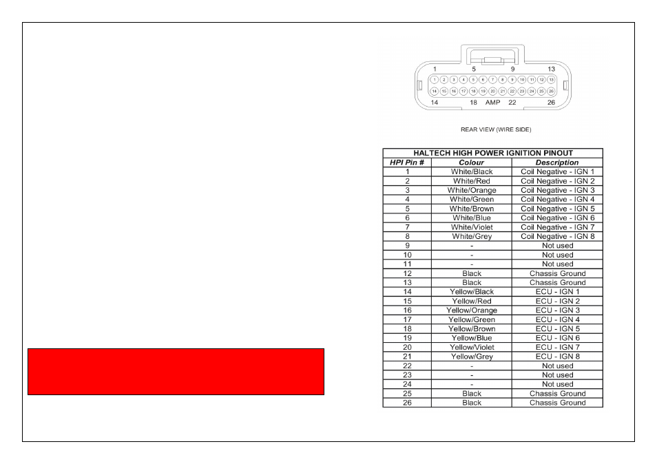
Appendix
Figure 9 – Haltech HPI Pinout Diagram
* WARNING!
Damage can occur to the Coil and/or the Haltech HPI if the
Dwell time is set to high. Please ensure your dwell time
is set based on the coil manufacturers recommendations.