Asus P4P800-X User Manual
Page 35
ASUS P4P800-X motherboard
1-25
13. System panel connector (10-1 pin PANEL)
This connector accommodates several system front panel functions.
P4P800-X
R
P4P800-X System panel connector
PANEL
*
Requires an ATX power supply.
PLED
PWRBIN
+5 V
+5V
Speaker
Speaker
Connector
Power LED
Ground
Reset SW
Ground
Reset
Ground
Ground
ATX Power
Switch*
HD_LED-
HD_LED+
IDELED
•
System Power LED Lead (Green 3-1 pin PLED)
This 3-1 pin connector connects to the system power LED. The LED lights up
when you turn on the system power, and blinks when the system is in sleep
mode.
•
System Warning Speaker Lead (Orange 4-pin SPKR)
This 4-pin connector connects to the case-mounted speaker and allows you to
hear system beeps and warnings.
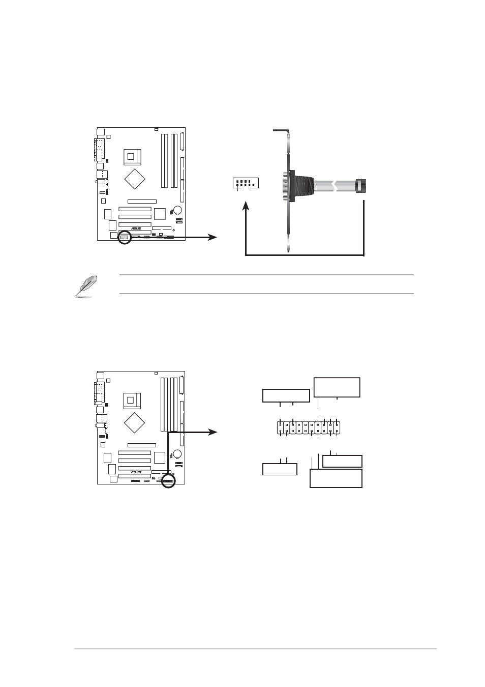
12. Serial connector (9-pin COM2 )
This 9-pin connector connects to a COM2 bracket. Connect the COM2 cable to
this connector and install the bracket on an available slot in the rear panel of
the chassis.
The COM2 bracket is purchased separately.
P4P800-X
®
P4P800-X Serial port connector
PIN 1
COM2
- Xonar DX (80 pages)
- Xonar DX (10 pages)
- PCI Express Audio Card Xonar DX (70 pages)
- Xonar D2X (88 pages)
- Xonar D2X (84 pages)
- D2X (88 pages)
- Audio Card Xonar D2X (70 pages)
- ROG Xonar Phoebus (72 pages)
- ROG Xonar Phoebus (122 pages)
- Xonar DSX (29 pages)
- Xonar DSX (26 pages)
- Xonar DGX (33 pages)
- Xonar DGX (58 pages)
- Xonar DGX (38 pages)
- Xonar DG (32 pages)
- Xonar DG (28 pages)
- Xonar DG (54 pages)
- Xonar DG (58 pages)
- Xonar Essence ST (52 pages)
- Xonar Essence ST (35 pages)
- Xonar Essence ST (40 pages)
- Xonar Essence ST (53 pages)
- Xonar DS (54 pages)
- Xonar DS (33 pages)
- Xonar Xense (45 pages)
- Xonar Xense (47 pages)
- Xonar Xense (70 pages)
- Xonar U3 (56 pages)
- Xonar U3 (38 pages)
- Xonar Essence STX (49 pages)
- Xonar Essence STX (10 pages)
- Xonar Essence STX (32 pages)
- Xonar D1 (10 pages)
- XONAR D1 E4009 (72 pages)
- Xonar D1 (72 pages)
- Xonar D1 (80 pages)
- Xonar Essence One (7 pages)
- Xonar Essence One (5 pages)
- Xonar HDAV 1.3 (100 pages)
- Motherboard M4A78-EM (64 pages)
- A7N8X-VM/400 (64 pages)
- K8V-XE (20 pages)
- K8V-XE (86 pages)
- M2R32-MVP (60 pages)
- M2R32-MVP (160 pages)