2 the rear panel, Mk equ215 rear panel - ii, Ii equ131- panel mk rear – Nilfisk-ALTO EQU MKII Series User Manual
Page 7
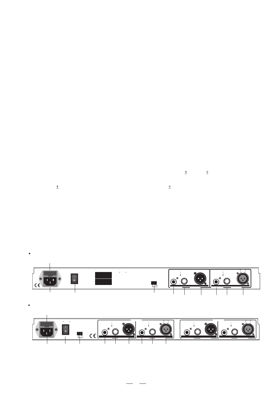
AC INPUT
95-120V
/210-240V
60-50Hz
Rated Power Consumption 9W
FUSE:
210-240V: T100mAL 250VAC
95-120V: T160mAL 250VAC
REPLACE FUSE WITH CORRECT
TYPE ONLY
Apparaten skall anslutas till
jordat uttag nar den ansluts
till ett natverk
GND
LIFT
ON
OFF
POWER
BALANCED
UNBALANCED
TIP/PIN 2
RING/PIN 3
SLEEVE/PIN 1
OUTPUT
BALANCED
UNBALANCED
TIP/PIN 2
RING/PIN 3
SLEEVE/PIN 1
INPUT
CHANNEL 1
BALANCED
UNBALANCED
TIP/PIN 2
RING/PIN 3
SLEEVE/PIN 1
OUTPUT
BALANCED
UNBALANCED
TIP/PIN 2
RING/PIN 3
SLEEVE/PIN 1
INPUT
CHANNEL 2
PUSH
2
1
3
NEW
TIDE
PUSH
2
1
3
NEW
TIDE
GND
LIFT
SERIAL
MODEL
ON
OFF
POWER
AC INPUT
95-120V
/210-240V
60-50Hz
Rated Power Consumption 9W
FUSE:
210-240V: T100mAL 250VAC
95-120V: T160mAL 250VAC
REPLACE FUSE WITH CORRECT
TYPE ONLY
Apparaten skall anslutas till
jordat uttag nar den ansluts
till ett natverk
BALANCED
UNBALANCED
TIP/PIN 2
RING/PIN 3
SLEEVE/PIN 1
INPUT
BALANCED
UNBALANCED
TIP/PIN 2
RING/PIN 3
SLEEVE/PIN 1
OUTPUT
6
3.2 The Rear Panel
MK
EQU215
Rear Panel
-
II
18
20
19
17
16
15
20
19
14
17
16
15
PUSH
2
1
3
NEW
TIDE
2.Level control
This control sets the input signal level to the equalizer. Its "0dB" position is unity gain (no boost or attenuation).
If the clip LED (5) is light continuously, turndown this control until it only flickers occasionally.
3.High pass filter
This button electronically inserts a filter into the signal path, which cuts the low frequencies at 40Hz (12dB per
octave). The LED (12) indicator lights when the button is pressed and this filter is serving in the circuit.
4.Low pass filter
This button electronically inserts a filter into the signal path, which cuts the high frequencies at 16KHz (12dB per
octave). The LED (13) indicator lights when the button is pressed and this filter is serving in the circuit.
5.Clip LED
This LED will light when any section of the equalizer is within 5 dB of clipping. Occasional flickering of this clip
LED is acceptable, but if it remains on continuously, you should turn down the level control or reduce the output
level of the preceding component to avoid audible distortion.
11.VU meter
This VU meter is used to indicate the output level.
12.High pass LED
When the High pass filter (40Hz/12dB) is in active, this LED will light.
13.Low pass LED
When the Low pass filter (16KHz/12dB) is in active, this LED will light.
8.EQ LED
When this LED lights, it is in EQ mode.
9.Range switch
This button switches the gain range of the filter potentiometer between 6dB and 12dB.
10.Filter range indicator
When the 6dB range is selected, green LED will light. When the 12dB range is selected, red LED will light.
7.EQ switch
This switch inserts or removes the equalizer to channel path. If press this switch, the EQ LED (7) will be illuminated,
which means it is in EQ mode. When release this switch, the input signal is routed directly to the output jacks.
which means it is in bypass mode.
6.Signal LED
This green LED will light when any signal appears at input/output stage.
18
17
15
16
II
EQU131-
Panel
MK Rear
14
17
16
15