Service and adjustments, Tine operation check (see fig.19) – Ariens 90203200 User Manual
Page 14
14
SERVICE AND ADJUSTMENTS
Fig. 19
TINE OPERATION CHECK (See Fig.19)
WARNING: Disconnect spark plug wire
from spark plug to prevent starting while
checking tine operation.
For proper tine operation, tine control lever must be against
control body and all slack removed from inner wire of control
cable when control is in the “OFF” (up) position.
If lever and cable are loose, loosen cable clip at lower end of
cable. Pull up on cable to remove slack, without extending
spring on end of cable, and retighten cable clip.
FINAL CHECK “OFF” POSITION
• With tine control “OFF” (up), push down on handle to
raise tines off the ground.
• Slowly pull recoil starter handle while observing tines.
Tines should not rotate.
• If tines rotate, inner wire of control cable is too tight
which is extending lower spring and engaging tines.
Loosen cable clip and push down on cable only enough
to relieve spring tension. Tighten cable clip.
• Recheck in “OFF” position and adjust if necessary.
FINAL CHECK “ON” POSITION
•
With tine control “ON” (held down to handle) push down
on handle to raise tines off the ground.
• Slowly pull recoil starter handle while observing tines.
Tines should rotate forward.
• If tines do not rotate, inner wire of control cable is too
loose. Loosen cable clip and pull cable up to remove
slack and retighten clip.
• Recheck in “ON” position and adjust if necessary.
NOTE: If “ON” position check required adjustment, re check
“OFF” position adjustment ensure tines do not rotate when
control is “OFF” (up).
TINE CONTROL
“ON” POSITION
TINE CONTROL
“OFF” POSITION
BODY
CABLE CLIP
TINE
CON TROL
CABLE
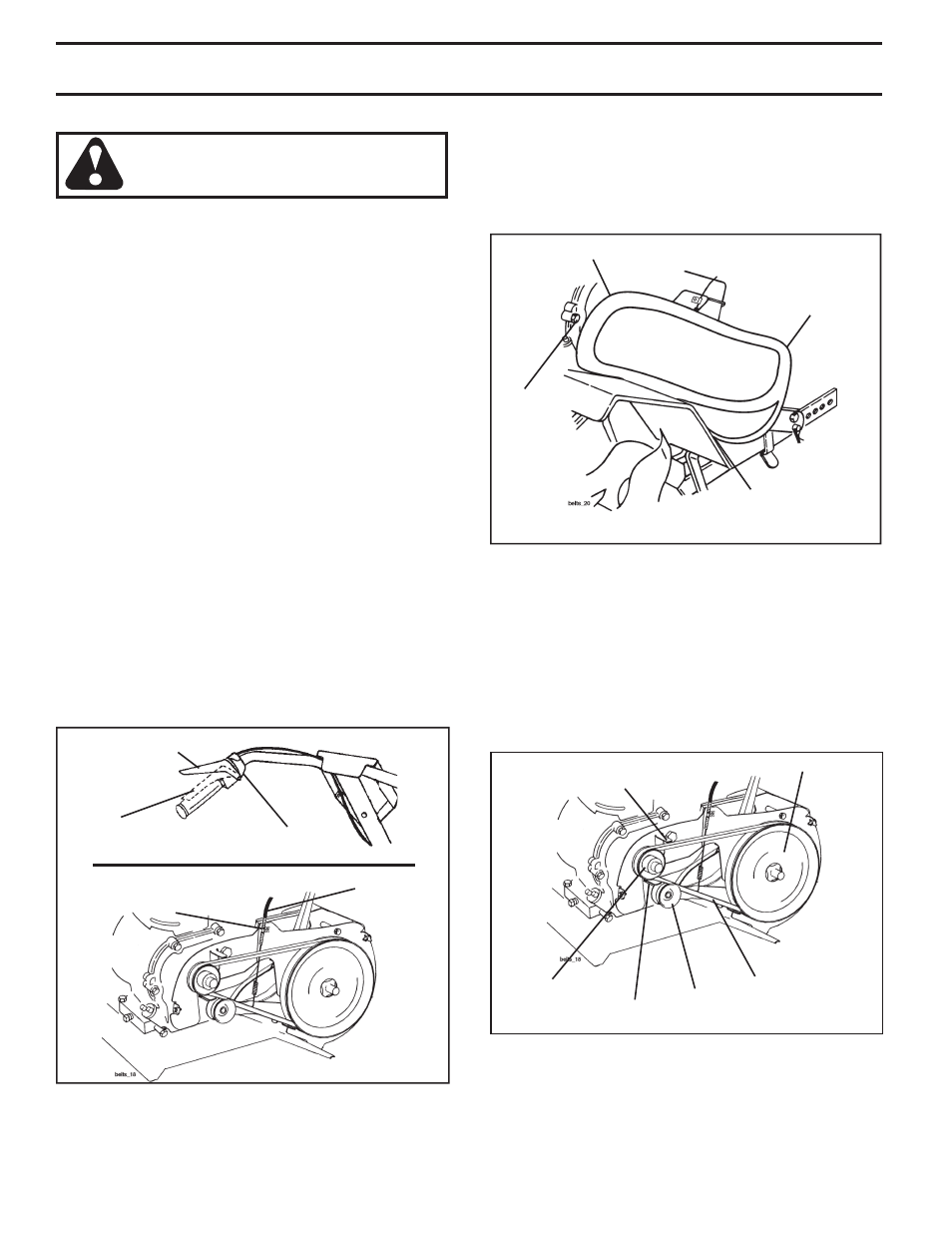
TO REMOVE BELT GUARD (See Fig. 20)
• Remove screws from side of belt guard.
• Pull belt guard out and away from unit.
• Replace belt guard by reversing above procedure.
Ensure slot in bottom of belt guard is under head of
tine shield bolt and all nuts are tightened securely.
Fig. 20
SCREW
BELT GUARD
SCREW
SCREW
TO REPLACE V-BELT (See Fig. 21)
Replace V-belt if it has stretched considerably or if it has
cracks or frayed edges.
Belt guard must be removed to service belt. See “TO RE-
MOVE BELT GUARD” in this section of manual.
BELT REMOVAL
• Remove V-belt from transmission pulley first and then
from engine pulley.
Fig. 21
V-BELT
IDLER
PUL LEY
TRANS MIS SION PUL LEY
BELT
GUIDE
ENGINE PULLEY
BELT
GUIDE