Assembly – Ariens 924551 - 8524 User Manual
Page 12
GB - 12
Tools Required:
• Pliers
• Open-End Wrenches: 3/8, 7/16, 1/2, 9/16"
and/or Adjustable Wrench
• Tire Gauge
PACKAGE CONTENTS
ASSEMBLY
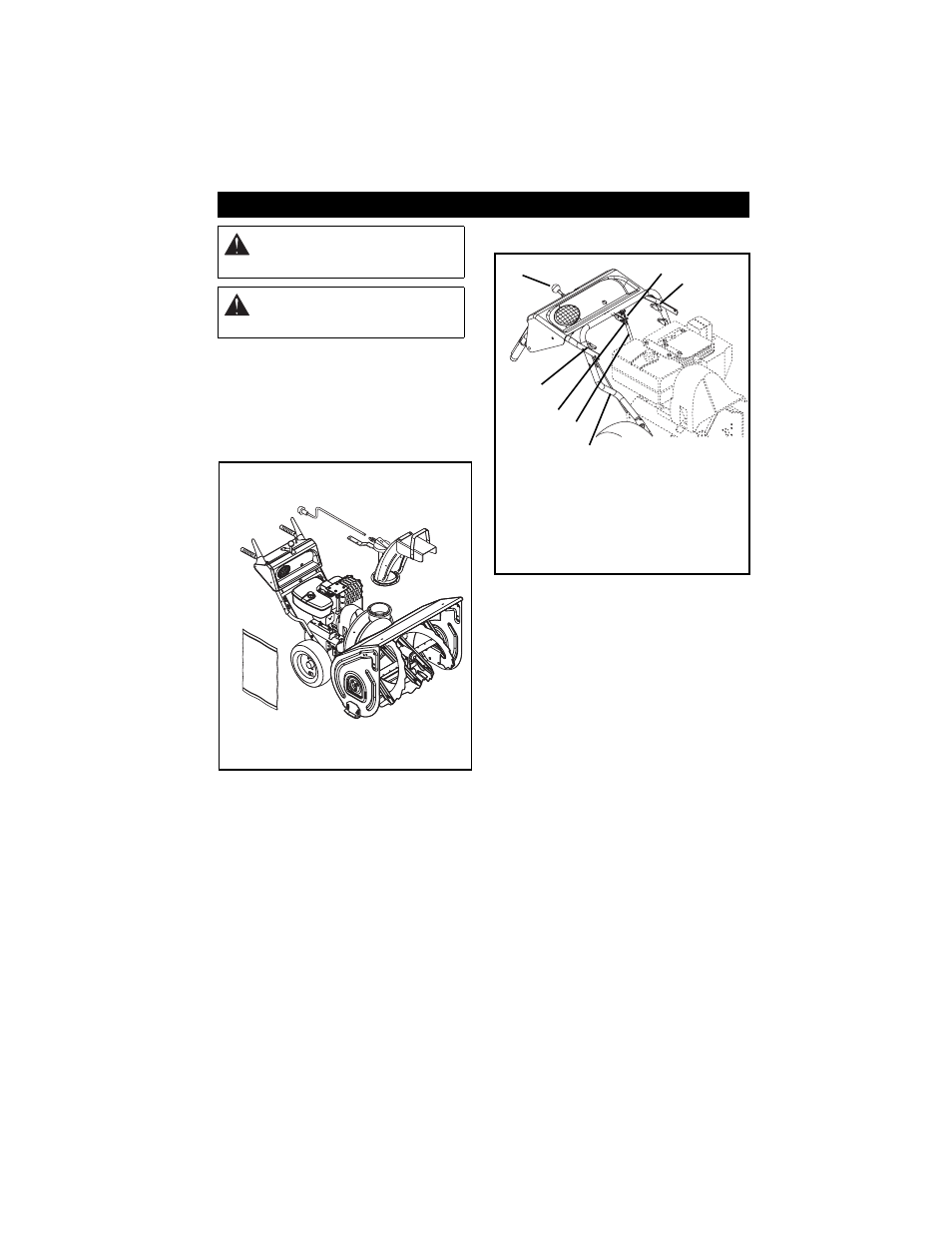
Handlebar and Shift Rod
1. Remove lower wing knobs on handlebar
assembly (Figure 5).
2. Remove upper wing nut and bolt on shift
rod.
3. Loosen upper wing knobs on handlebar.
4. Loosen lower wing nut and bolt on shift
rod.
5. Put speed selector lever into fastest
reverse panel notch.
6. Rotate handlebar up so wing knob holes
align. Install and tighten all wing knobs.
7. Install wing nut and bolt removed in step 2
onto shift rod and tighten hardware.
Install Discharge Chute and Crank
(924118, 121, 122, 332, 508, 551)
1. Grease discharge chute ring on blower
housing (if not already greased).
2. Remove mounting hardware from top of
engine.
3. Slide chute ring under retainer clip on
blower housing and put chute on housing.
4. Secure chute by fastening chute strap to
engine with hardware just removed.
NOTE:
Washers and lock nuts go on top of
chute strap.
5. Loosen mounting nut on chute and move
chute up or down so that chute ring is
approximately centered between retainer
clip and lower ring and tighten.
6. Slide chute crank rod through bracket
under handlebar and through hole in
panel.
7. Align chute crank rod with the universal
joint on chute and fasten with spring clip.
ASSEMBLY
WARNING:
AVOID INJURY. Read
and understand the entire
Safety
section before proceeding.
WARNING:
Dropping or tipping over
boxed unit could result in personal
injury or damage to unit.
Literature
Pack
Figure 4
Chute Crank (924121,122,
118, 332, 508, 551)
Discharge
Chute
Sno-Thro
Unit
OS1642
1. Handlebar
Assembly
2. Wing Knobs
3. Wing Nut
4. Speed Selector
5. Bolt
6. Shift Rod
1
2
4
5
6
Figure 5
3
OS0901
2