Example: sub station # chart – Aiphone 83873900 0602 E User Manual
Page 14
Sub's Block
& Number
Block #
Subs #
Bathroom
Pullcord
Yes or No
Corridor lamp
Yes or No
Urgent
Call Sw.
Yes or No
Zone #
Assigned
– 14 –
3. INSTALLATION & WIRING
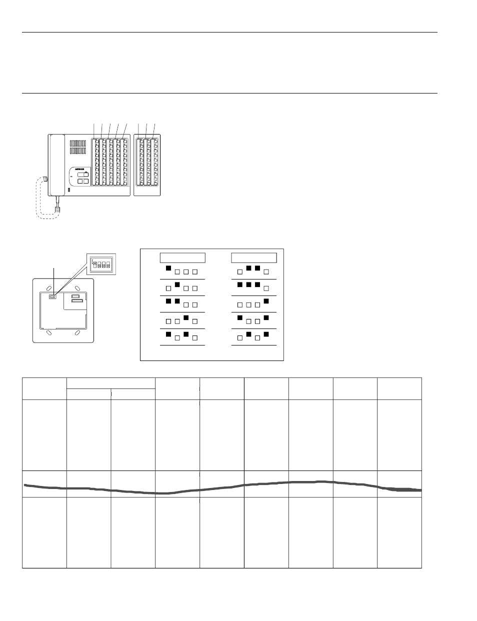
Ⅵ Setting Station #1 ~ 10 on Sub stations
Before installing sub stations:
1. Make a SUB STATION # CHART (Fig. 2), assigning sub station numbers to each room where sub will
be installed.
2. Move 4 dip switches (1 ~ 4) on the back of the sub station according to the # chart.
• NHX-50M master station
FIG.1
As shown in Fig. 1, the vertical rows of Call buttons are
assigned sub station #1 ~ 10 (from top) of Trunks 1 - 5
from the left on NHX-50M.
NHX-30G controls Trunks 6 ~ 8.
• Sub stations
Sub # Set switches: Initially all in OFF position. Move to upper ON position, according to the Chart.
Example: #7 : 1 + 2 + 4 = 7
* Do not assign the same number for
more than one sub within a trunk.
Otherwise, system will malfunction.
FIG. 2
BLOCK 1-1
2
3
4
5
6
7
8
9
10
1
1
2
3
4
5
6
7
8
9
10
(NHR-3TS own)
(Staff call)
1
BLOCK 1-1
2
2
1
2
2
BLOCK 8-1
2
3
4
5
6
7
8
9
10
8
1
2
3
4
5
6
7
8
9
10
(NHR-3TS own)
4
Zone # 1 ~ 4: Assigned by wire terminations of Sub‘s ZL terminal.
Corresponding terminals are Z1 – Z4 on NHX-80X).
Bedside
Toilet
NHX-50M
Blocks
Station Nos.
NHX-30G
Master station
Add-on selector
1 from top
1
2
3
4
5
6
7
8
10
9
8
7
6
5
4
3
2
Seting Sub station #
DIP switches
NH-1SA,NH-2SA,
NHR-3TS
Back view
SW1
The dip switches marked 1, 2, 3, 4 should read 1, 2, 4, 8
1 2 4 8
1
2
3
4
5
1 2 4 8
6
7
8
9
10
Example: Sub station # Chart
Powered from
NHX-80X
Powered from
NHX-80X
Type of Subs