Typical system connections -13 – ASA Electronics 856 User Manual
Page 13
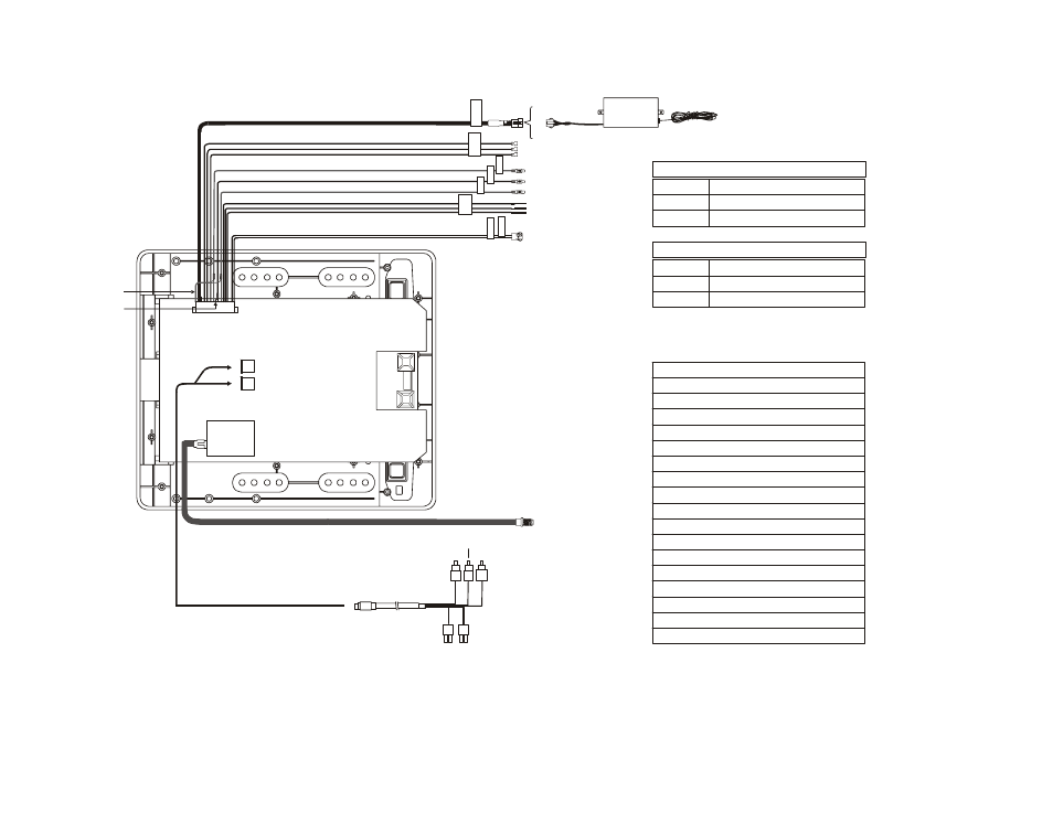
TYPICAL SYSTEM CONNECTIONS
-13-
1
2
3
4
5
6
12
10
7
8
9
15
16
17
13
14
TO
FM
TR
A
N
S
M
IT
TE
R
SPEA
K
ER
OR
HE
A
D
P
H
O
N
E
CO
NN
E
C
T
IO
N
LI
NE
O
U
T-
R
LI
N
E
O
U
T
-V
LI
NE
O
U
T-
L
TW
O
D
O
M
E
LI
G
H
T’
S
C
O
NNE
CT
IO
N
P
O
W
E
R
(+
12V
)
PO
W
ER
(GN
D
)
PIN 2 – Power GND/Black
PIN 3 – Dome Light Auto/White
PIN 4 – Light GND/Black
PIN 5 – Dome Light B+ /Red
PIN 6 – Line Out (L)/White
PIN 7 – Spk Out (R) /Green
PIN 8 – Spk Out-GND/Black
PIN 9 – Spk Out (L)/Grey
PIN 10 – Video Out/Yellow
PIN 11 – Video GND/Black
PIN 12 – Line Out (R)/Red
PIN 13 – Power 12V(FM Trans.)/Red
PIN 14 – Power GND (FM Trans.)/Black
PIN 15 – Audio (L) Out (FM Trans.)/White
PIN 16 – Audio GND (FM Trans.)/Black
PIN 17 – Audio (R) Out (FM Trans.)/Red
PIN 18 – Line Out GND/Black
PIN 1 – Power/Red
White - Entry Switch/Negative
Black - Constant + 12VDC/Dome
Red- Chassis Ground
Negative Dome Light Switching
White - Entry Switch/Positive
Black - Chassis Ground
Red- Constant + 12VDC/Dome
Positive Dome Light Switching
White RCA(Audio Left)
Red RCA(Audio Right)
Yellow RCA(Video)
4 PIN
Power
Connector
2 PIN IR
Connector
Accessory
Harness
18
11
49 MHz
FM Transmitter