Signal inputs – Audiovox LCMR6CT User Manual
Page 8
WARNING:
Observe polarity when connecting the wires.
Figure 4
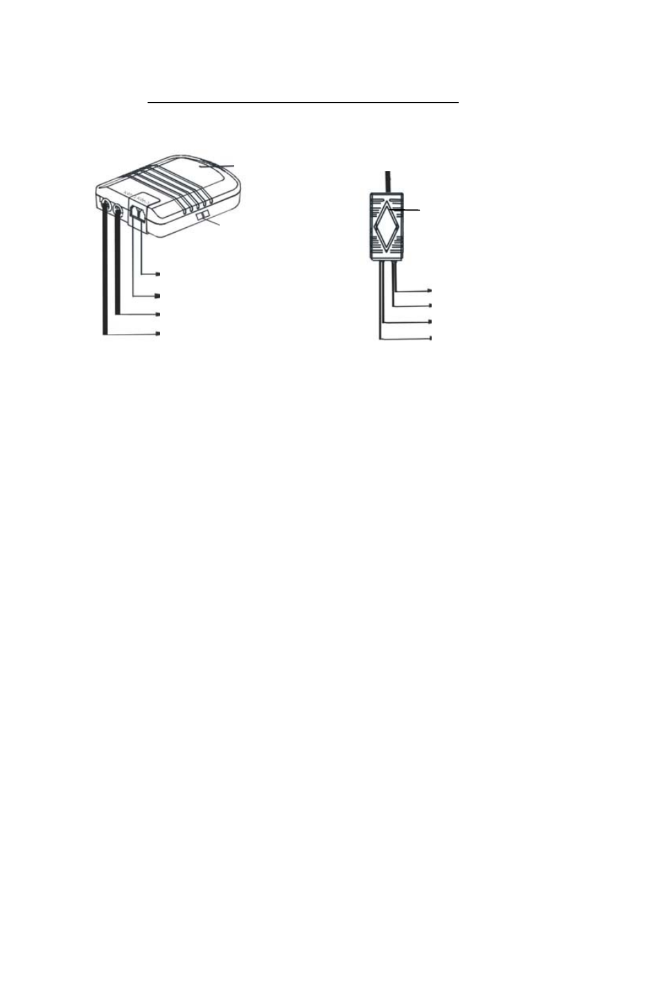
2. Signal Inputs
The signal input connections for the system include:
Control BOX
To Control BOX
Filter BOX
Cam Button
Selector Switch
To Rearview Camera
To Interior Camera
To Mirror Assembly
To Filter BOX
Red (+12V)
Blue (Ignition)
Black (GND)
Green (Reverse)
(1) Rear Camera: Plug the RJ 11 camera cable end into the control box
AVin-1 location, route the cable to the rear camera and plug the 4-pin
connector into camera 4 pin connector. Users can see the rearview camera
image when the car is shifted into reverse.
(2)
Interior Camera: Plug the RJ 11 camera cable end into the control box
AVin-2, Users can see the interior camera image when the “CAM” button is
pressed.
(3) Compass Sensor: Connected directly to mirror.
(4) Temperature Sensor: Connected directly to mirror.
(5) Navigation: The navigation signal is supplied via the monitor cable
plugged directly into the rear of the mirror.
7