Armstrong World Industries A50CU User Manual
Page 22
AR-EXP-CUMMINS-07-00
OWNERS MANUAL
then be removed the
generator will remain on load until either the ‗STOP/RESET‘
or ‗AUTO‘ positions is selected.
Auto
This button places
the module into its
‗Automatic‘
mode.
This mode allows the
module to control the function of the generator automati-
cally. The module will monitor the remote start input and
the mains supply and once a start condition is signaled the
set will be automatically started and placed on load (‘Load
transfer’ becomes active (if used)). If the starting signal is
removed or the mains supply returns, the module will auto-
matically transfer the load from the generator and shut the
set down observing the stop delay timer and cooling timer
as necessary. The module will then await the next start
event. For further details please see the more detailed de-
scription of ‘Auto Operation’ earlier in this manual.
Test
This mode is used
to allow on load test of the
generator
func-
tions. Once in Test mode
the module will
respond to the start (I)
button and start the engine and run on load until either the
‗STOP/RESET‘ or ‗AUTO‘ positions is selected.
Start
This button is
only active in MANUAL or TEST
modes. Pressing this button in manual mode will start the
engine and run off load. If the generator is running offload
in the Manual mode and a remote start signal becomes
present or the mains supply returns, the module will auto-
matically instruct the changeover device to place the gen-
erator on load (‘Load transfer’ becomes active (if used)).
Should the remote start signal then be removed the genera-
tor will remain on load until either the ‗STOP/RESET‘ or
‗AUTO‘ positions is selected.
Power Up LCD display
When DC power is first applied to the 5120 controller, a
short LCD test is per-
formed that illuminates all
LCD segments. After this,
the module‘s software
revision number is shown
briefly.
For example, this display
is showing software revi-
sion 1.00
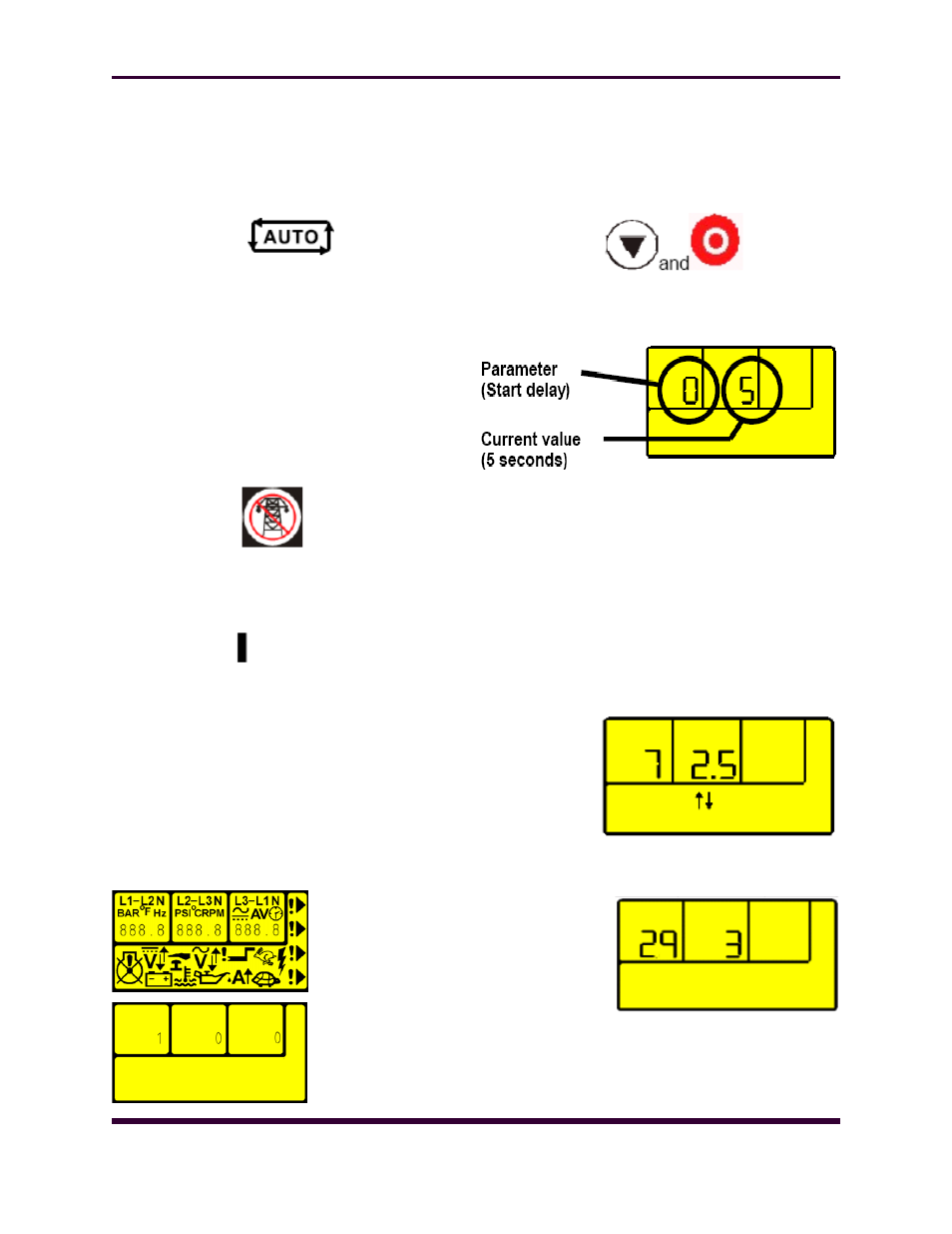
ENTERING CONFIGURA-
TION MODE
NOTE:- Configuration mode can ONLY be entered when the
module is in the STOP mode and the engine is at rest.
Press the DOWN and STOP buttons to enter configura-
tion mode.
The first configurable parameter is displayed. In this ex-
ample, the Start delay timer (parameter 0) is currently set
to 5s.
Editing Analog Values
Enter the front panel configuration editor as described pre-
viously. Press the button to enter adjust mode. When in
adjust mode (indicated by the flashing icons in the module
display), pressing the + or – buttons will change the se-
lected parameter to the desired value. Press the button
to ‗save‘ the value. The icons will stop flashing to confirm
that it has been saved.
To select the next parameter to edit, press the + button.
Continuing to press the + / – buttons will cycle through the
adjustable parameters in the order shown in the following
lists. Timers display in seconds up to 59 seconds, then in
minutes up to the timer‘s maximum value. For instance, the
parameter being
displayed in this
example is the
c ooling
t im er
(parameter 7). It‘s
current value is
2.5mins
(2mins
30secs).
7.5 EDITING A ‗LIST‘ VALUE
Some configuration
parameters have a
list of options to se-
lect from. These in-
clude input and out-
put settings.
This example shows
the setting for LCD
i n d i c a t o r
3
(parameter 29). It‘s current setting is 3 (‗Close Generator‘
from the lists shown below.)
NOTE:- When in adjust mode (indicated by the flashing
icons in the module display), pressing the (stop mode) but-
Page 22