Armstrong World Industries A50CU User Manual
Page 20
AR-EXP-CUMMINS-07-00
OWNERS MANUAL
Typical LCD screens
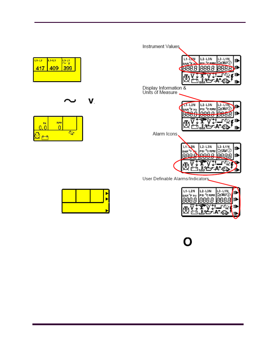
Instruments
The LCD displays the various engine parameters such as
‗ENGINE SPEED‘, ‗OIL PRESSURE‘, ‗HOURS RUN‘, etc. Each
instrument is displayed with
the appropriate units of meas-
ure. In this example, the values
being displayed are Generator
phase to phase AC voltages
Alarm Icons
The LCD also
d i s -
plays the exact nature
of any alarm condition that may have occurred such as LOW
OIL PRESSURE using appropri-
ate icons. This allows very
specific alarm conditions to
be brought to the operators‘
attention. Refer to the
‗Protections‘ section of this
manual for details of the
alarms.
User Defined Indications
The LCD displays the user-defined indications when config-
ured and active. The icons will illuminate and point to the
appropriate text insert label. These indications can be used
to indicate internal states (i.e. Engine Running, Safety On,
etc).
User Defined
Alarms
The LCD displays the user-defined alarms when configured
and active. The icons will illuminate and point to the appro-
priate text insert label. These alarms can be used to indi-
cate the operation of external alarms (i.e. ‗Low Fuel Level‘,
‗Low Coolant level‘ etc) or to indicate internal alarms (i.e.
Fail to Stop, MPU fault, etc).
LCD Display Areas
NOTE:-
The
Engine
Hours Run counter will only
display the accumulated
hours to the nearest 12
Minutes (0.2Hr). The
accumulated time will be
recorded in HH:MM however.
CAUTION:
If the DC supply to the module is interrupted the hours run
counter will not remember any ‗undisplayed‘ minutes accu-
mulated since the last 12 Minute display update.
i.e.
10 Hours 38 Minutes accumulated before DC supply is
removed… (10.6 Hours displayed) would become …10
Hours 36Minutes on restoration of DC supply. (10.6 Hours
still displayed) This will only occur in the event of a total DC
supply break and will NOT occur if the module is simply
switched to the Stop/Reset position.
VIEWING THE INSTRUMENTS
Page 20