Fan failure safety lock-out circuit – AutoFlo S2020 User Manual
Page 11
C
EW
CONTROLS INC.
Excellence Without Compromise
R
APPLICATION NOTE
AN 147 FAN FAILURE SAFETY
LOCK-OUT CIRCUIT
“Field Provided”
EWC Controls Inc. 385 Highway 33 Englishtown, NJ 07726 800-446-3110 732-446-3110 FAX 732-446-5362
.
.
.
.
.
R
W
G
Y
TYPICAL
THERMOSTAT
R
W
G
Y
C
FURNACE
HUMIDISTAT
G1
R
G2
H
H
S2000 & S2020 HUMIDIFIER
NO
NO
NC
C
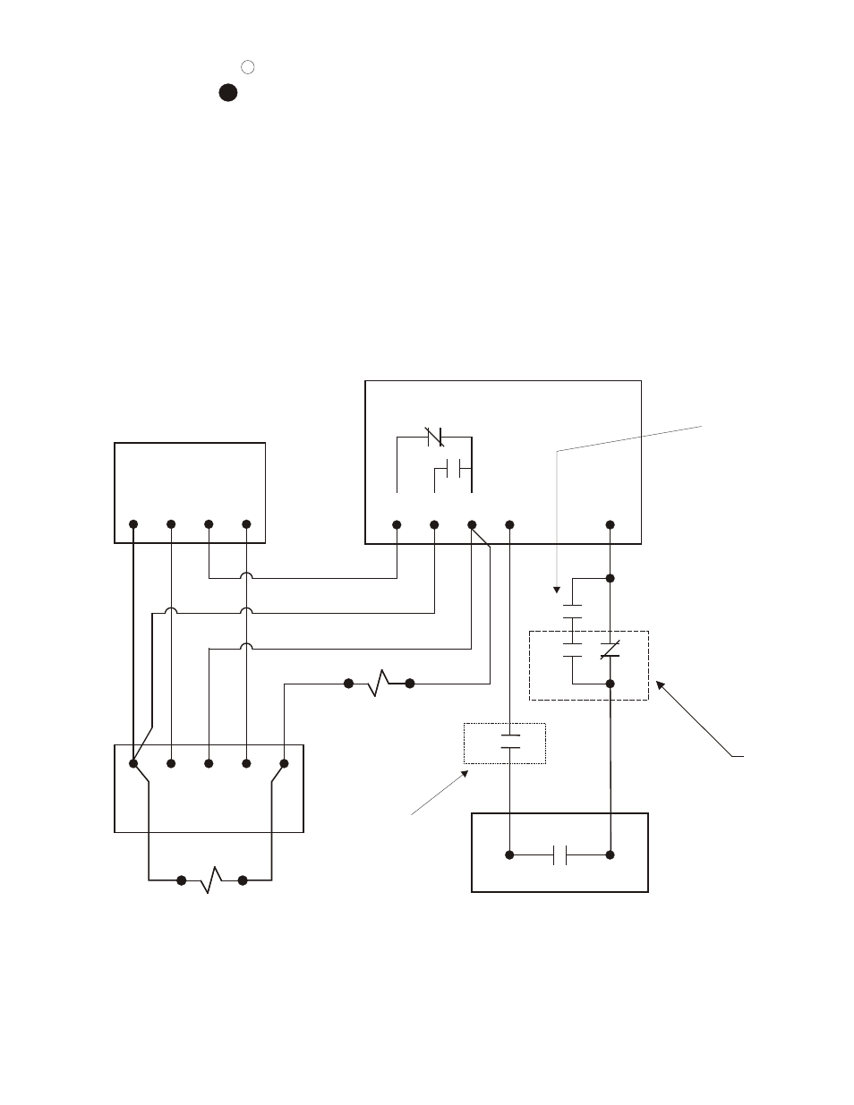
FAN FAILURE SAFETY LOCK-OUT CIRCUIT
SEPARATE
SAIL SWITCH
OR
CURRENT SENSING
RELAY CONTACTS
SPDT
K1 Interlock
Basic RELAY
24 VAC COIL
The use of a safety lock-out circuit is highly recommended. The circuit below is effective at
stopping the humidifier operation if the fan motor fails for any reason. The use of a system
interlock is optional and not required for basic operation. Failure to incorporate a lock-out
can result in excessive condensation inside the duct work and/or possible flood damage,
if the HVAC Fan/Blower fails to operate. This solution is provided as a supplement. Flood or
water damage as a result of not using this diagram is not the responsibility of EWC Controls.
K1 COIL
K2 COIL
SPST
K2 Interlock
Optional RELAY
24 VAC COIL
NO