Setup and operation, Programmable absorption timer switch continued, Installation – Wesley BC-6200-8SAC User Manual
Page 7
6
S e t u p a n d o p e r a t i o n
Setup and Operation
1) Install your On Board Solutions battery charger by referring to Page 9 of this manual.
2) After installation is complete including AC and DC connections please ensure proper
strain relief of all AC and DC wiring has been performed.
3) Apply AC power, you should see the following:
A. Battery Type selection LED will illuminate and is controlled by the battery type selector
switch. (Shown on Page 7)
B. Charging LED will illuminate until battery voltage reaches 80% battery charged threshold.
The Conditioning LED will then illuminate.
C. Conditioning LED will remain on for 2-6 hours determined by the Conditioning
timer switch.
D. After 2-6 hours the Conditioning LED will turn off and the Ready LED will illuminate
indicating that the battery(s) are fully charged and are being maintained in the float
maintenance mode and are ready for use.
E. In Ready mode the batteries are maintained at the selected battery voltage and will
supply power for loads of any type up to the maximum output of the charger.
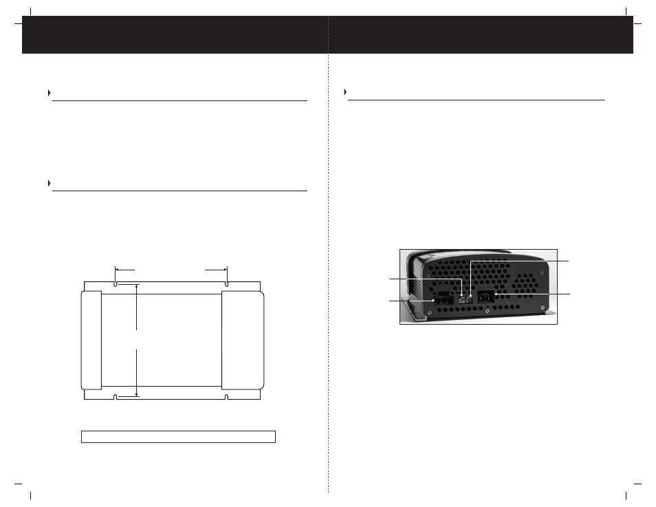
Shown Above - Conditioning and Battery Type Selector Switches. Please refer to Pages 7
and 8 for settings and selections.
After the Fast Charge cycle, Conditioning time is determined by the Conditioning timer switch
shown in the figure above.
Full-rated current is available in Ready Mode. Voltage will normally be above charged battery
voltage at full output.
Note: The charger is equipped with an internal temperature sensor that will shutdown the
charger if internal temperature reaches unsafe levels.
Note: Your ProTech-C charger is equipped with a fan, which is temperature controlled and
will only run when cooling is necessary.
Your On Board Solutions charger is self current limiting with built in: over temperature, over
voltage, and reverse polarity protected.
Note: If you wish to manually restart (recycle) a charge sequence from the beginning, simply
disconnect and then reconnect AC power via the power cable.
9
I n s t a l l a t i o n
Programmable Absorption Timer Switch Continued
Please note: Nominal measurement
Stainless steel mounting screws and hardware not included
Interlock/
Inhibit Quick
Disconnect
connector
Battery Type
Selector Switch
(Shown with
switch cover
removed)
Conditioning
Time Selector
Switch
Charger DC
Output Quick
Disconnect
connector
Installation
1) Make sure to mount the charger in a dry or weatherproof / ventilated location with
easy access. Remember to leave plenty of room for battery cables and AC wiring.
2) Six inches of clearance minimum is required on all sides to allow for adequate
ventilation for proper cooling.
3) Use the ProTech-C as a template for drilling four 1/8” pilot holes. Stainless Steel self
tapping screws (3/16 x 1-1/4” are recommended) or drill four 3/16” through holes if
using 3/16” through bolts with washers, lock washers and nuts.
THE PROTECH-C CHARGERS AUTOMATICALLY ADJUST FOR 120 VOLT OR 240 VOLT
AC INPUT POWER.
NOTE: Recommendation assumes charger is rated at 10% of battery system Amp/Hour
rating. (Example: 15 amp charger being used on 150 A/H rated system). Use the battery
20A/H system rating to determine. A 6 hour setting is available for larger system amp/hour
applications [i.e. 325 A/H] or when 10% rule is exceeded. Consult the factory if you are
unsure of what your setting should be. A 4 hour timer switch setting is typically used on 220
A/H system batteries.
4 15/16" (125mm)
6 3/16" (173mm)