Section 3. sensor alignment and installation, 1 alignment, Sensor alignment and installation -1 – Campbell Scientific ST350 Strain Transducer for Structural Testing User Manual
Page 9: Alignment -1, 1. measurement axis -1
Section 3. Sensor Alignment and
Installation
3.1 Alignment
The BDI ST350 will only measure strain in the axis in which it is aligned with,
therefore the more accurate the alignment, the more accurate the measurements
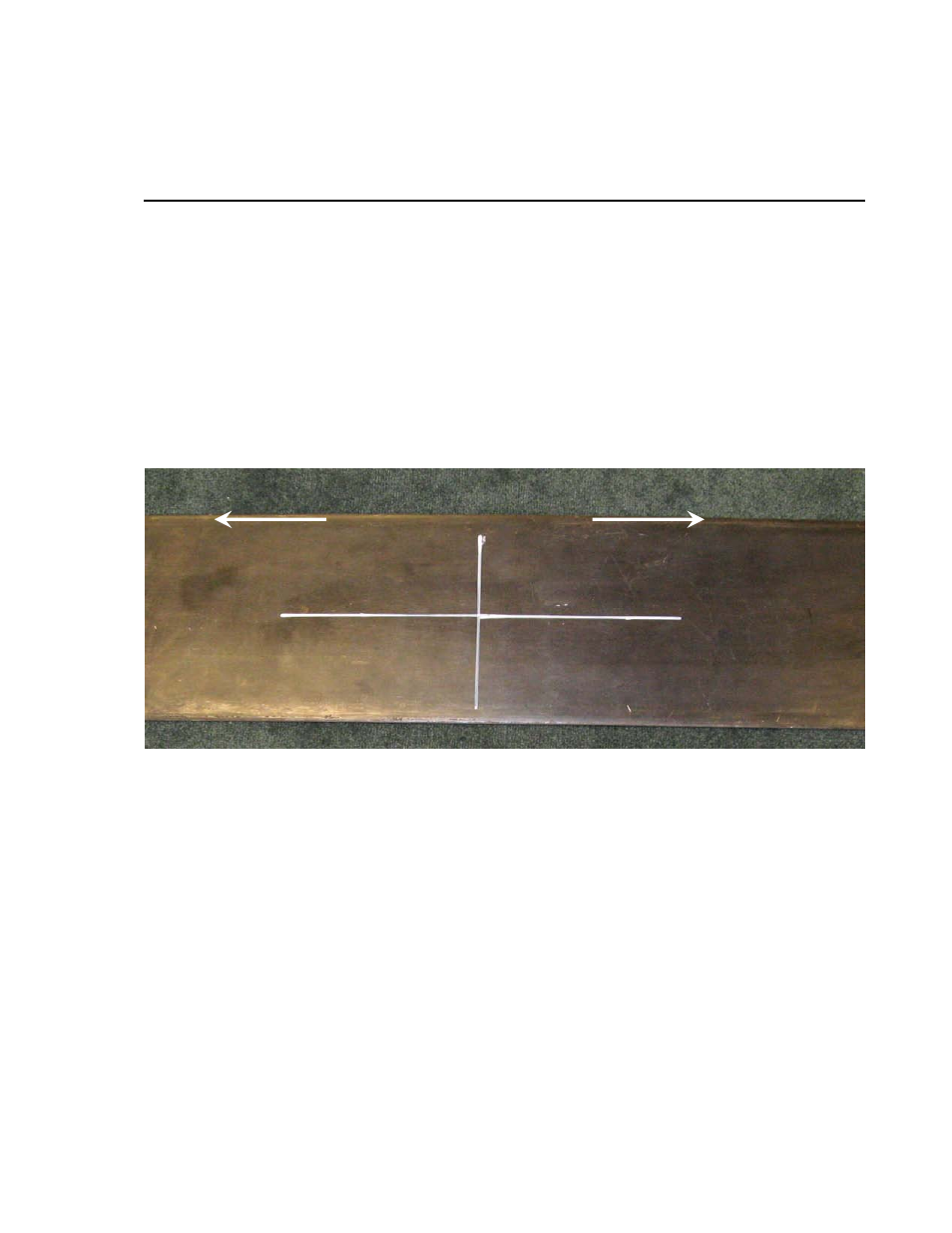
will be. The easiest way to align a transducer is to mark a “grid” type pattern
for both the proper foot placement and measurement axis. First, locate the
center-line of the gaging area in both the longitudinal and transverse directions.
For example, if measurements are to be obtained at the mid-span of a joist,
locate the midpoint between the supports and the center-line of the joist. The
longitudinal mark should be about 8 inches long and the transverse mark about
4 inches long. This will allow the marks to be seen while the transducer is
being positioned. This can be seen in the picture below.
M
EASUREMENT
A
XIS
FIGURE 3-1. Measurement Axis
From the transverse mark, make two additional marks at 1.5 inches on either
side of the centering mark (see below photo). The areas circled below are the
portions of the cross-section that the necessary surface preparations must be
performed. Surface preparation techniques are explained in Section 5:
Mounting of sensor to various surfaces.
3-1