2 rs-485 – Campbell Scientific LR4 Four Channel Latching Relay Module User Manual
Page 16
LR4 Four Channel Latching Relay Module
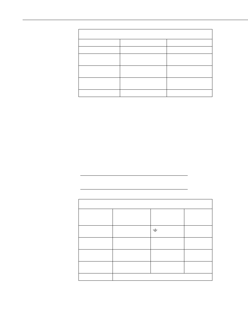
TABLE 2. Modbus/RS-232 Wiring
LR4 Terminals
Description
Datalogger Terminal
GND
Power Ground and Shield G
POWER
Positive DC Power
Source (9-30VDC)
12V
SDI-12 /TX/A
Modbus master RS-232
Receive
COM port (Rx)
RX/B
Modbus master RS-232
Transmit
COM port (Tx)
DIG I/O
Not used
Not used
8.1.2 RS-485
The CR800, CR850, CR1000, CR3000, CR510, CR10X, and CR23X
dataloggers can use Modbus via RS-485. Please note that the CR510 and
CR10X require a Modbus operating system.
With the RS-485 mode, one MD485 Multidrop Modem is required. The
MD485 connects to the LR4 via the CABLE2TP cable and connects to the
datalogger via the 18663 Null Modem Cable. Also required is the 14291 Field
Power Cable to connect the LR4 power terminals to the MD485.
The DIG I/O port on the LR4 is not used. Table 3 shows the wiring. For more
information about using the MD485, refer to the MD485 Multidrop Modem’s
manual.
Your system should be powered down before wiring the
LR4.
CAUTION
TABLE 3. Modbus/RS-485 Wiring
LR4 Terminals
Description
MD485
Terminal
14291 Field
Cable Wire
Color
GND
Power Ground and
Shield
Black
POWER
Positive DC Power
Source (9-30VDC)
N/A Red
SDI-12 /TX/A
Modbus master
(RS-485A)
A N/A
RX /B
Modbus master
(RS-485B)
B N/A
DIG. I/O
Not Used
10