2 sdi-12 addresses, 3 sdi-12 commands – Campbell Scientific LR4 Four Channel Latching Relay Module User Manual
Page 11
LR4 Four Channel Latching Relay Module
7.2 SDI-12 Addresses
The LR4 can be set to one of ten addresses (0 to 9) which allows up to ten LR4
modules to be connected to a single digital I/O channel (control port) of an
SDI-12 datalogger.
The LR4 is shipped from the factory with the address set to 0. The address on
the LR4 can be changed by sending an SDI-12 change-address command. The
change address command can be issued from most SDI-12 recorders. For
some Campbell Scientific dataloggers, the SDI-12 transparent mode will need
to be entered to change the address.
When it is necessary to use more than one LR4, it is easiest to use a different
control port for each LR4 instead of changing the address. If additional control
ports are not available, then the address will need to be changed.
To change the address of an LR4 with the default address of 0 to the address of
1, the following command can be sent:
“0A1!”
Only one SDI-12 device should be connected when using the change address
command.
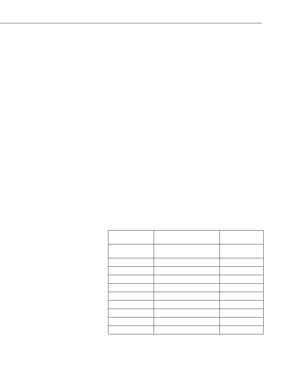
7.3 SDI-12 Commands
The SDI-12 protocol has the ability to support various measurement
commands. The LR4 supports the commands that are listed in the following
table.
The different commands are entered as options in the SDI-12 recorder
instruction. The major difference between the various measurement commands
are the data values that are returned.
SDI-12 extended commands are used to set a relay to a desired state.
SDI-12 Command
Command
Function/Description
Values Returned
aM!
Status All 4 Relays - 0 or 1
State
R1, R2, R3, R4 (4
values)
aM1!
Status Relay #1 - 0 or 1 State
R1
aM2!
Status Relay #2 - 0 or 1 State
R2
aM3!
Status Relay #3 - 0 or 1 State
R3
aM4!
Status Relay #4 - 0 or 1 State
R4
aM5! LR4
Supply
Voltage
V
Supply
(Volts)
aM6!
Not completed – Do not use
aM7!
Not completed – Do not use
aM8
!
Dig. I/O input state – 0 or 1
Dig. I/O Input State
aM9
!
Not completed – Do not use
5