Configuring the inputs, Configuring system information, Configuring email notification – Chatsworth Products Remote Infrastructure Management (RIM-1000) User Manual
Page 2: Completing the installation
©2014 Chatsworth Products, Inc. All rights reserved. Chatsworth Products, CPI, CPI Passive Cooling, eConnect, MegaFrame, Saf-T-Grip, Seismic
Frame, SlimFrame, TeraFrame, GlobalFrame, Cube-iT Plus, Evolution, OnTrac, QuadraRack and Velocity are federally registered trademarks of Chats-
worth Products. Simply Efficient is a trademark of Chatsworth Products. All other trademarks belong to their respective companies. 7/14 MKT-60020-619
While every effort has been made to ensure
the accuracy of all information, CPI does not
accept liability for any errors or omissions
and reserves the right to change information
and descriptions of listed services and
products.
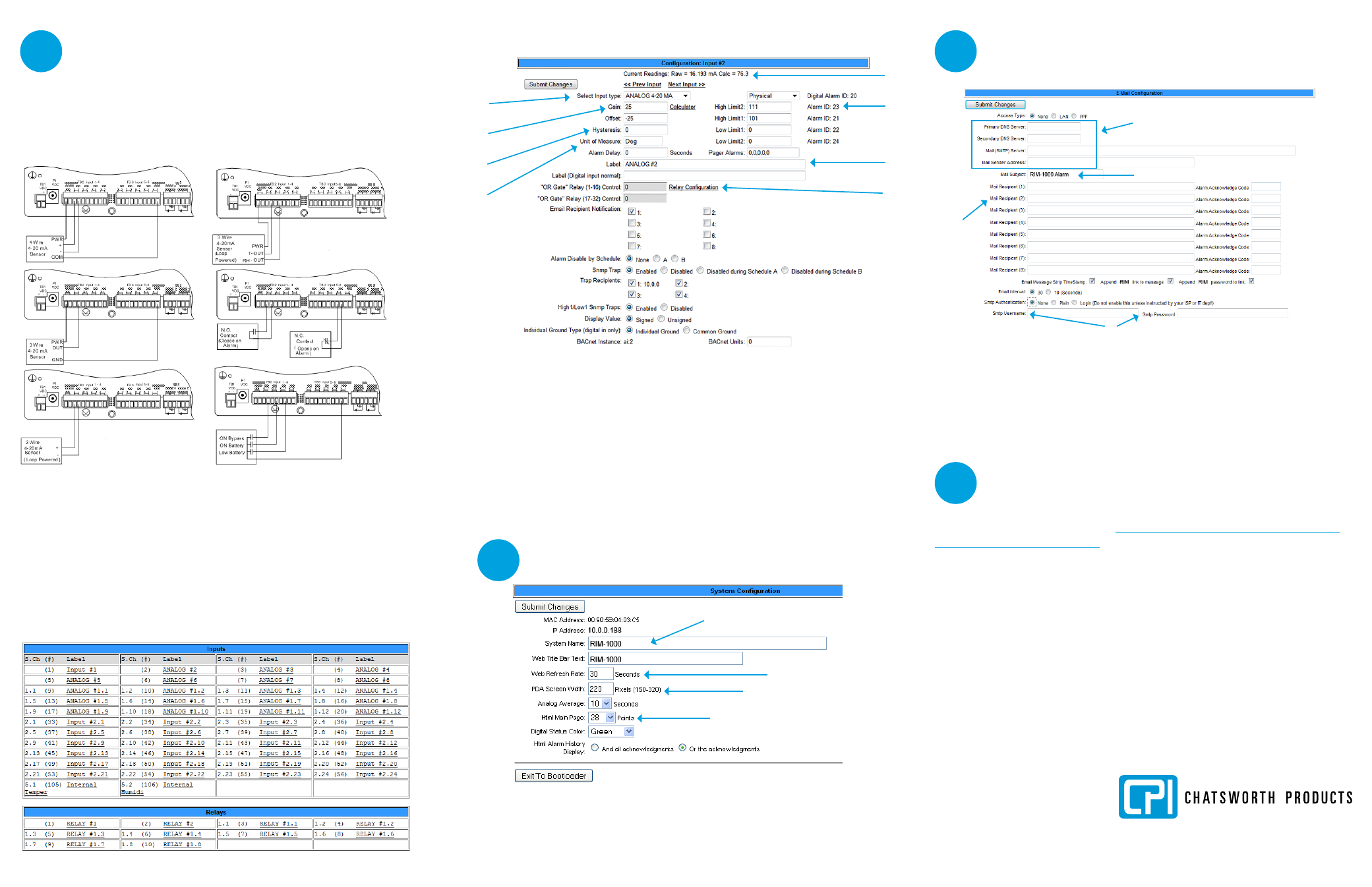
Configuring the Inputs
The eight non-isolated universal inputs are connected to TB2 and TB3.
Universal input channels can be individually configured through the RIM-
1000 to monitor a 4-20mA signal, a normally open (NO) dry contact relay or
a normally closed (NC) dry contact relay.
Making the Physical Connections
The following figure shows examples of input wiring.
Once you have wired the inputs, make note of the following:
•
Sensor type (analog or digital) connected to each channel.
•
For analog sensors, the high/low values.
•
For digital sensors, the non-alarm state - normally open (NO) or normally closed
(NC).
Configuring the Channels
Configure the input channels using the Inputs & Relays page of the RIM-1000 web
inteface. Click on the underlined label for the input you want to configure.
Configuring Inputs
A
Input can be Analog 4-20 mA or Digital NO or NC.
B
Applies only to analog inputs. Gain and offsett determine the correct
value for the RIM-1000.
C
Applies only to analog inputs. Hysteresis designates the amount an input
must change before returning to normal.
D
Applies only to analog inputs. Displays units on main menu, such as Deg F,
Deg C, %RH, Amps, Volts, psi, etc.
E
RIM-1000 current raw reading and calculated value.
F
Applies only to Analog inputs. High and Low alarm thresholds of range
being monitored.
G
This label is displayed on the RIM-1000 menu and the configuration menu.
H
Relay configuration link.
A
B
C
D
E
F
G
H
Configuring System Information
A
An alphanumeric name that you would recognize. This name appears on
the Main Menu and is included as part of email and pager notifications.
B
An integer greater than 5.
C
Consult your PDA manual for the correct width.
D
The number of points to be monitored. Maximum 104.
A
B
C
D
Configuring Email Notification
The RIM-1000 sends one email message per alarm instance to a maximum
of eight email recipients.
A
Refer to information from IT administrator.
B
Text that is easily recognized as notification from the RIM-1000.
C
Up to eight email recipients.
D
For ESMTP email authentication. Refer to information from IT
administrator.
A
B
C
D
Completing the Installation
Once you have completed the tasks in this quick start guide, the RIM-1000
can communicate over the network and monitor the inputs you configured.
Consult the RIM-1000 User Manual at
tasks:
•
System clock settings
•
Network time protocol settings
•
SNMP/Syslog settings
•
Modbus/Telnet settings
•
BACnet settings
•
User administration
•
URL links to IP-addressable devices
•
Nest/Egg configuration (for additional RIM-1000 appliances that will be
monitored by a central RIM-1000 appliance)
•
Trends
•
Alarm management
Common 4
Wire Sensors
Common 3
Wire Sensors
IE: CPI P/N
60111-001, 60111-002
Temperature Sensor
IE: CPI P/N
60111-004/60111-005
Temperature/
Humidity Sensor
IE: CPI P/N
60110-001
Power Fail
Monitor
IE: Common
Ground for
UPS
IE: CPI P/N 60109-001,
Spot Detector
4
5
6
7