Installation, Operation, Problem solving – Samlex America VTC305 User Manual
Page 4
INSTALLATION
MOUNTING
Mount the unit in a DRY location. Allow at least 1 inch of clearance for adequate cooling.
POWER CONNECTION
The unit is supplied with three foot power input leads. This should normally be adequate to con-
nect to a source of power. If you must extend the cable:
•
Use the smallest extension length possible.
•
Use no less than 10 gauge conductors.
•
Splice and solder the joints.
•
Protect the joints with heat shrink tubing.
Connect the wires as follows:
•
Red to Positive
•
Black to Negative
OUTPUT CONNECTIONS
Two positive output terminals and two negative output terminals are provided. Connect only one
wire to each terminal. Ensure that the total average load connected does not exceed the continu-
ous current rating of the unit.
Note that the current specifications are for input current. To obtain the maximum output current
capability at any given input voltage, use the following formula:
Output Current = Input Volts / Output Volts x 27
For example:
10 VDC in and 27 VDC out, the max output current = 10/27 x 27 = 10.0 Amps.
20 VDC in and 27 VDC out, the max output current = 20/27 x 27 = 20.0 Amps
OPERATION
Turn the power switch on the front of the unit on to energize the outputs.
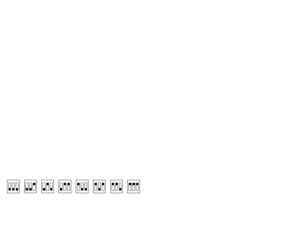
To adjust the output voltage, turn off the power switch. Remove the plate from the top of the box.
Reach in with a non-conductive device such as a pencil and open or close the dip switches as
shown below to select the desired output voltage. Replace the plate. Turn the power switch on.
3.
MINIMUM
BLACK PORTION INDICATES SWITCH IS PUSHED DOWN
+0.5V
+1.0V
+1.5V
+2.0V
+2.5V
+3.0V
+3.5V
PROBLEM SOLVING
•
If the load exceeds the continuous rating for too long a period, the internal tem-
perature sensor will cause the unit to stop boosting the input voltage until the unit
has cooled down. After the unit has cooled down, normal operation will resume.
•
If the input voltage drops below the specified minimum input, the unit will sound
the alarm.
•
If the output voltage drops below the specified minimum, the unit will sound the
alarm.
•
If the current demanded by the devices connected to the unit exceed the maxi-
mum current rating, the fuse will blow.
•
If the fuse blows with no load connected, check that the power leads are con-
nected to the battery with the correct polarity; if they are then the unit is damaged
and must be returned for repair.