Introduction, Specifications – Samlex America VTC305 User Manual
Page 2
INTRODUCTION
Step up a 12 VDC battery to between 13.5 and 17.0 or 24.0 and 27.5 VDC in 0.5
VDC increments (via 3 position DIP switch), or stabilize a 12 or 24 VDC power sys-
tem. Safety features include reverse input protection, low input voltage alarm, low
output voltage alarm, over temperature shutdown and alarm, and output over voltage
crowbar. If the input voltage exceeds the regulated output voltage, the unit simply
passes the voltage through with full LC filtering and a single schottky diode drop (0.5
VDC or less). Optional features include a dry contact alarm relay output, and remote
panel monitoring with On/Off control.
Applications include temporarily brightening 12 volt headlights or work lights, increas-
ing voltage into an automotive or marine ignition system for hotter spark and/or pre-
vention of failures due to voltage drop during engine start, stabilizing 12 and 24 VDC
power systems in marine, automotive or aeronautical environments and more.
SPECIFICATIONS
Specifications subject to change without notice.
1.
Model
VTC305-12-12
VTC305-12-24
Input Voltage
10.5 - 18 VDC
10.5 - 28 VDC
Output Voltage
Input – 1V or 13.5 - 17.0 VDC
Whichever is greater
Input – 1V or 24.0 - 27.5 VDC
Whichever is greater
Current Limit
30 Amps In
Output Crowbar
16.0
± 0.5 V
32.0
± 1.0 V
Input Fuse
AGC 20 x 2 Amp
Low Input Voltage
Alarm
10.5 VDC
Low Output Voltage
Alarm
Programmmed Output Volt-
age minus 2.5 VDC
Noise on Input
< 25 milli-volts
Noise on Output
< 25 milli-volts
Transient Resp.
< 1V for 15A Surge
Efficiency
> 90 % @ maximum output
Temp. Range
0 - 40 deg
° C @ maximum
output
Isolation
Any Input or Output to Case
500VDC
Input to Output Common
Negative
Length
9.1 in / 23.1 cm
Width
7.8 in / 19.8 cm
Height
2.5 in / 6.4 cm
Clearance
1 Inch (2.5 cm) all around
Material
Marine Grade Aluminum
Finish
Black Powder Epoxy
Fastenings
18-8 Stainless
Weight
4.0 lb / 1.8 kg.
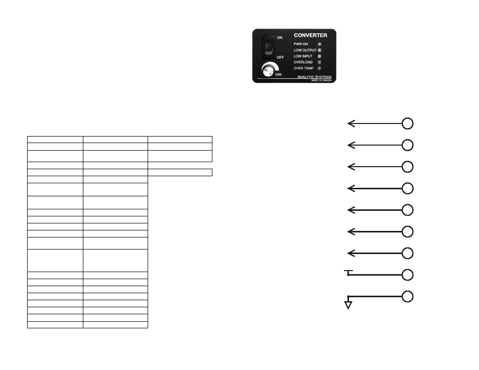
REMOTE CONTROL (OPTIONAL)
A remote control panel may be connected to the con-
verter using a 9-pin D-connector, which attaches to the
side of the converter. The remote control panel and D
connector are part of the remote control option. The
remote control panel allows the unit to be operated re-
motely as well as duplicating all the diagnostic indicators
and audible alarm.
REMOTE CONNECTOR
This connector is located on the side of the unit.
Note: All switches are electronic (solid state) not mechanical relays.
6.
6
7
3
4
2
1
8
9
5
DRY CONTACT
ALARM RELAY
DRY CONTACT
ALARM RELAY
GROUND
COMMON FOR SWITCHES
REFERENCE VOLTAGE
FOR REMOTE OFF
+12 VDC
REMOTE OFF
CONNECT TO 5 TO FORCE
UNIT TO OFF
OVER TEMP
NORMALLY HIGH (+12V)
GOES LOW ON
OVER TEMPERATURE
LOW INPUT
NORMALLY HIGH (+12V)
GOES LOW WHEN
INPUT GOES LOW
OVERLOAD
NORMALLY HIGH (+12V)
GOES LOW WHEN
UNIT OVERLOADED
LOW OUTPUT
NORMALLY HIGH (+12V)
GOES LOW WHEN
LOW
OUTPUT GOES