Technical data – Siemens DE2427415 User Manual
Page 15
9
en
Remove the flow-rate limiter (see Fig. A) with low water
■
pressure.
Explain the operation of the continuous-flow heater to
■
the user.
A
If the continuous-flow heater does not have sufficient
water flow due to low water line pressure in your do-
mestic plumbing system, remove the flow-rate
limiter.
B
Priority circuit for the combination with electrical
storage heaters:
For operation with a priority circuit, a special load
shedding relay BZ 45L20 (special accessory) is re-
quired. Other existing load shedding relays, with the
exception of electronic load shedding relays, may
malfunction.
C
The control electronics must be coded when operated
with a load shedding relay.
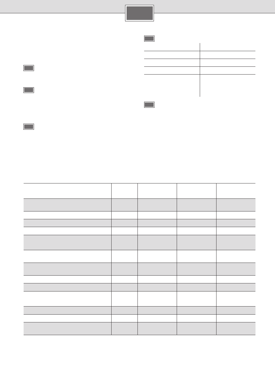
Technical data
DE 12415
DE 1821415
DE 4151821
DE 2427415
DE 4152427
Rated output
[kW]
13.2
18
21
24
27
Rated voltage
[V]
400
400
400
Fuse protection
[A]
20
32
40
Minimum conductor cross-section
[mm
2
]
4
4
6
Warm water flow at rated output
with temperature increase from
12 °C to 38 °C
[l/min]
7.3
9.9
11.6
13.2
13.9
12 °C to 60 °C
[l/min]
3.9
5.4
6.3
7.2
7.6
Start-up flow
[l/min]
2.6
2.6
2.6
Start-up flow pressure *
[MPa (bar)]
0.025 (0.25)
0.025 (0.25)
0.025 (0.25)
Application area in water
specific electric resistance at 15 °C
[Ωcm]
≥ 1 300
≥ 1 300
≥ 1 300
Rated pressure
[MPa (bar)]
1.0 (10.0)
1.0 (10.0)
1.0 (10.0)
Maximum permissible supply temperature
[°C]
55
55
55
Maximum mains impedance at connection
point
[Ω]
≤ 0.244
≤ 0.244
≤ 0.244
* The pressure loss on the mixer must also be added
D
Status display on the appliance
LED
Appliance status
Off
Off
Lights up
Ready
Slow flash (1/s)
Appliance is heating
Fast flash (4/s)
Desired water temperature
is not reached (water flow
too high for appliance
rating).
E
The filter upstream from the check valve in the cold
water supply inlet is clogged.
Remove the filter and either clean it or descale it.
See Figure E 1–3.