Matrix Orbital PK202-25 User Manual
Page 10
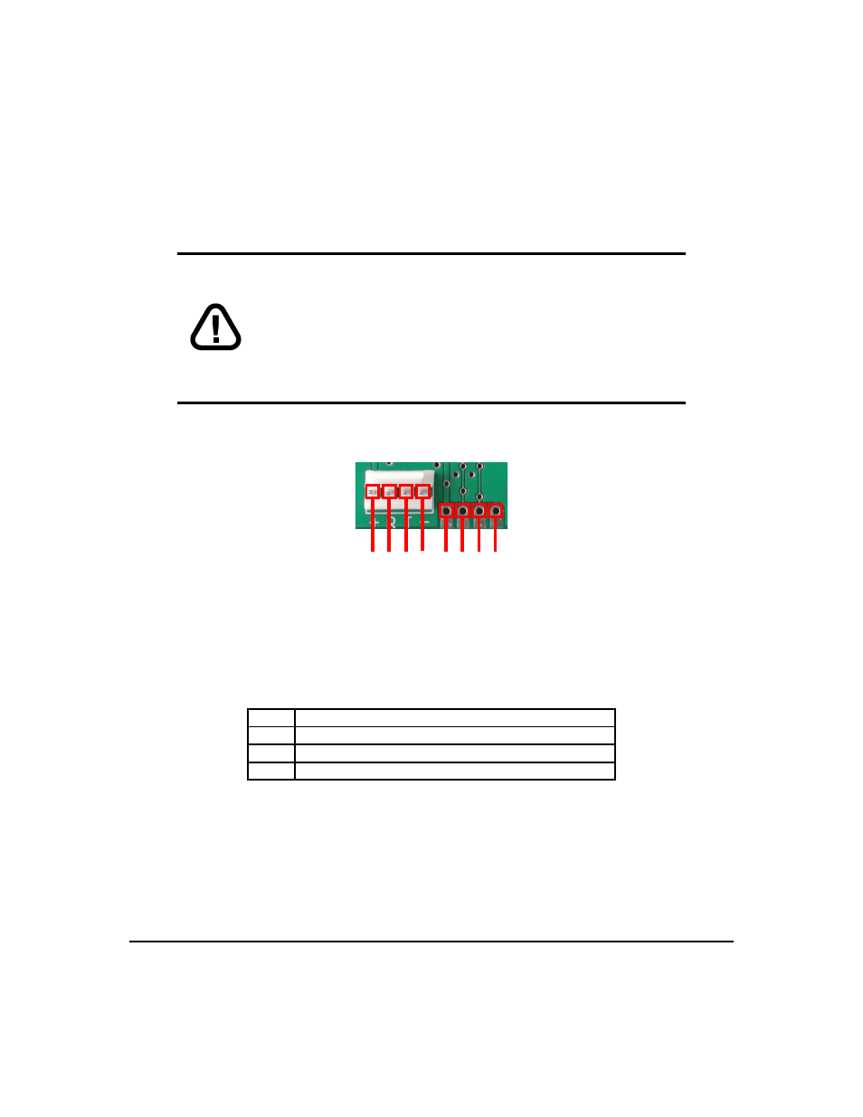
2.1.1 Power Connections
Power is applied via pin1 and ground via pin 4 as shown in the figure below. Power requirement is +5
VDC ±0.25V. As an alternate power conncetion, power may also be supplied via the RS-232 connector as
described in section 2.1.4.
WARNINGS
• Do not apply any power with reversed polarization.
• Do not apply any voltage other than the specified voltage.
• Do not use any cables other than the cables supplied by Matrix
Orbital, unless aware of the modifications required.
• Do not apply voltage to the DB-9 connector AND power connector
• Do not apply more than +5Vdc to pin 9 on the DB-9 connector.
Connector pinout is as follows:
1 2 3 4 1 2 3 4
Figure 3: Power Connector
Table 3: Connector Pinout
Pin 1
+5.0 VDC (+7 to +15 VDC with wide voltage option)
Pin 2
SCL (I
2
C clock), Rx
Pin 3
SDA (I
2
C data), Tx
Pin 4
Ground
2.1.2 Five Volt Modules
If the display is used in a PC it becomes tempting to plug a spare power connector into the unit.
Don’t
do this! Wiring for the PC power connector and that required for the display are different as shown in the
Figure below.
Matrix Orbital
PK202-25
6