6 hardware, 1 standard model, Communication/power header – Matrix Orbital MOS-AL162F User Manual
Page 10: Alternate communication/power connector, Protocol select jumpers
10
6 Hardware
6.1 Standard Model
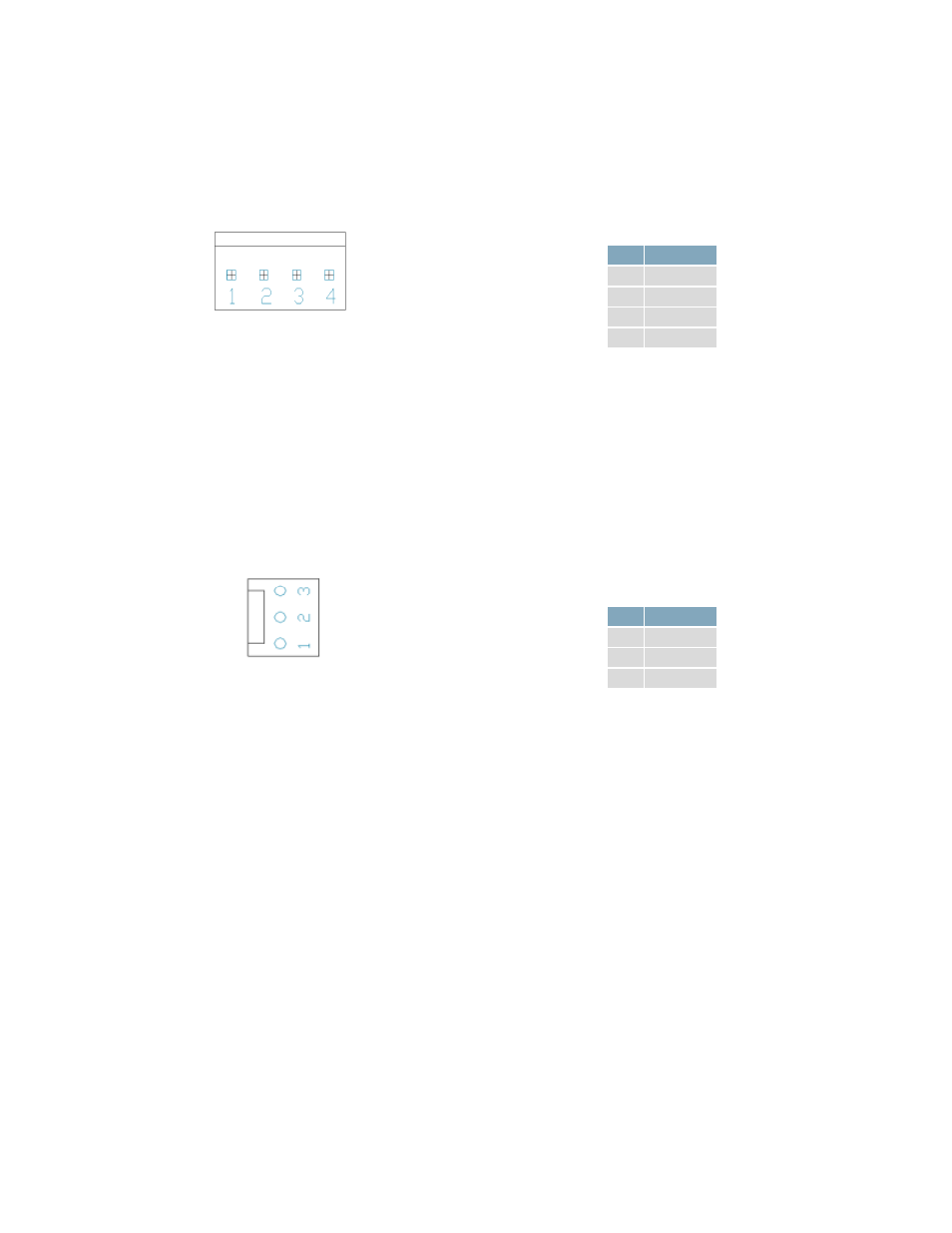
Communication/Power Header
Figure 6: Communication/Power Header
Table 4: Communication/Power Pinout
Pin Function
1
Vcc
2
Rx
3
Tx
4
Gnd
The Communication/Power Header provides a standard connector for interfacing to the serial series
MOS-AL162F. Voltage is applied through pins one and four of the four pin Power/Data connector.
Please ensure the correct voltage input for your display by referencing the electrical specifications in
Table 13 before connecting power. Pins two and three are reserved for serial transmission, using either
RS-232 or TTL logic levels, depending on what has been selected by the Protocol Select Jumpers.
Alternate Communication/Power Connector
Figure 7: Alternate Power Connector
Table 5: Alternate Power/Data Pinout
Pin Function
3
VCC
2
Rx
1
Gnd
The MOS-AL162F also provides a three pin version of the Power/Data Connector which permits the
device to receive commands only, no response is possible. The Molex 22-27-2031 style header is
particularly useful for connecting to an unmodified floppy power cable, a Molex 22-01-2031 for
example, from a PC power supply for a simple bench power solution.
Protocol Select Jumpers
The Protocol Select Jumpers, provide the means necessary to toggle the display module between RS-232
and TTL protocols. As a default, the jumpers are set to RS-232 mode with jumps on the 232 jumpers. In
order to change the display to TTL mode, simply remove the zero ohm resistors from the 232 jumpers
and solder them to the TTL jumpers.