Features, Hardware, Drawing – Matrix Orbital MOP-GL12232B User Manual
Page 4: Interface
3
Features
The Matrix Orbital Parallel display series offers a low cost display solution utilizing an industry standard
communication interface for simple integration into a wide variety of new and existing applications. The
Light Emitting Diode backlight with configurable brightness and voltage controlled contrast allows the
MOP Liquid Crystal Display line to offer a professional display solution for any project.
Hardware
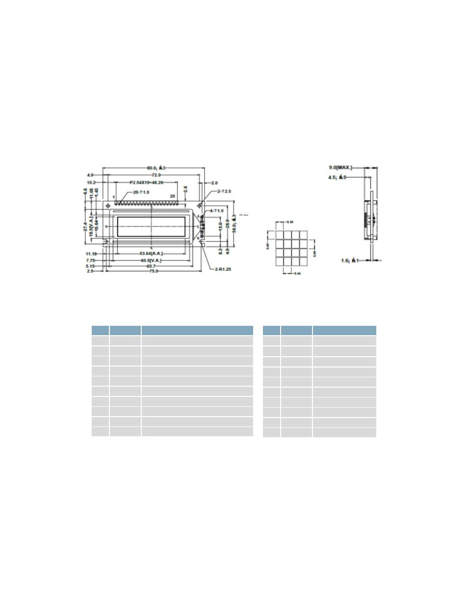
Drawing
Figure 1: MOP-GL12864F Mechanical Drawing
Interface
Table 1: Display Control
Pin Symbol
Description
1
V
SS
Ground
2
V
DD
Supply Voltage for Logic
3
V
0
Supply Voltage for LCD (Contrast)
4
RS
Register Select
5
CS1
Chip Enable (Left)
6
CS2
Chip Enable (Right)
7
CL
Clock
8
E
Enable
9
R/W
Read/ Write
18
RST
Reset
Table 2: Parallel Data and Backlight
Pin Symbol
Description
10
DB0
Data bit 0
11
DB1
Data bit 1
12
DB2
Data bit 2
13
DB3
Data bit 3
14
DB4
Data bit 4
15
DB5
Data bit 5
16
DB6
Data bit 6
17
DB7
Data bit 7
19
LED (+)
Backlight Anode
20
LED (-)
Backlight Cathode