Pc wiring display module wiring – Matrix Orbital VFD2041 Legacy User Manual
Page 8
VFD2041 rev 2
8
Connector pinout is as follows:
1 2 3 4
Figure 2-2 Power connector
Pin 1
+5.0 VDC (+8 to +15 VDC with wide voltage option)
Pin 2
SCL (I
2
C clock)
Pin 3
SDA (I
2
C data)
Pin 4
Ground
2.1.1.1 Five Volt Modules
If the VFD2041 is used in a PC it is tempting to plug a spare power connector into the unit. Don't do this!
Wiring for the PC power connector and that required for the VFD2041 are different as shown in Figure 2-3
below.
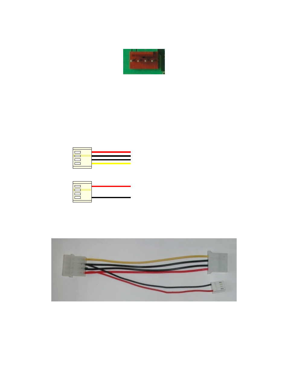
PC wiring
Display module wiring
+5 V
+5 V
GND
GND
+12 V
Figure 2-3 Power Connector wiring differences
If you don't want to modify cable wiring yourself, Matrix Orbital can supply an adapter cable designed to
use with the VFD2041 when it's installed in a PC. The cable is wired as shown in Figure 2-4 below. Note
that this cable does not provide connections for I
2
C.
Figure 2-4 Five volt Power Cable
- GTT35 (19 pages)
- GTT50A (53 pages)
- GTT70A (19 pages)
- GTT38A (19 pages)
- GTT43A (19 pages)
- GTT50A (19 pages)
- GTT Example Files (2 pages)
- GX24064 (24 pages)
- GLT24064R-1U (72 pages)
- GLT24064 (71 pages)
- GLT24064 Legacy (56 pages)
- GLK24064-25 Legacy (41 pages)
- GLK24064-25 Legacy (47 pages)
- GLK24064-25 Legacy (68 pages)
- GLT240128 (70 pages)
- GLT240128 Legacy (70 pages)
- GLK12232-25-SM (70 pages)
- GLK12232-25-SM Legacy (41 pages)
- GLK12232-25-SM Legacy (42 pages)
- GLK12232-25-FGW (66 pages)
- GLK19264A-7T-1U (68 pages)
- GLK240128-25 Legacy (67 pages)
- GLC24064 (44 pages)
- GLC24064 (63 pages)
- GLK12232-25-WBL (39 pages)
- GLK19264-7T-1U (71 pages)
- GLK24064-16-1U (48 pages)
- VK162-12 (41 pages)
- LK162-12 Legacy (37 pages)
- LK162-12 Legacy (42 pages)
- LK162A-4T (36 pages)
- LK162B-7T (37 pages)
- VK202-25-USB (42 pages)
- LK202-25 Legacy (20 pages)
- LK202-25 Legacy (37 pages)
- LK202-25 Legacy (50 pages)
- VK204-25 (47 pages)
- LK204-25 Legacy (33 pages)
- LK204-25 Legacy (62 pages)
- LK204-7T-1U (40 pages)
- LK402-25 (43 pages)
- LK402-25 Legacy (56 pages)
- LK404-25 (37 pages)
- LK202-24-USB (36 pages)
- LK202-24-USB (48 pages)