3 applying power via the rs-232 connector, 4 configuring rs-232 and i – Matrix Orbital LCD0821 Legacy User Manual
Page 10
LCD0821 rev 2
10
The RS-232 connector on the PC cable is wired so that a standard “straight through” serial cable may be
used to connect the module to a standard serial port such as COM ports on PCs. Note that this device
complies with the EIA232 standard in that it uses signal levels from ± 3V to ± 12V. It will not operate
correctly at TTL (0 to +5V) levels.
Pin Number
on LCD
Pin Number
on Host
Direction
Description
1 N/A
-
+5Vdc
2
3
to LCD module
Data In
3 5
- Ground
2.1.3 Applying Power via the RS-232 Connector
The power connector on the PC cable is wired as shown in Figure 2-7. Power may be provided to the
module by pin 1 of the 3pin strip header connector instead of through the 4-pin SIP. If power is to be
applied using the 3 pin strip header.
2.1.4 Configuring RS-232 and I
2
C
RS-232 baud rate and I
2
C address are configured by means of jumpers.
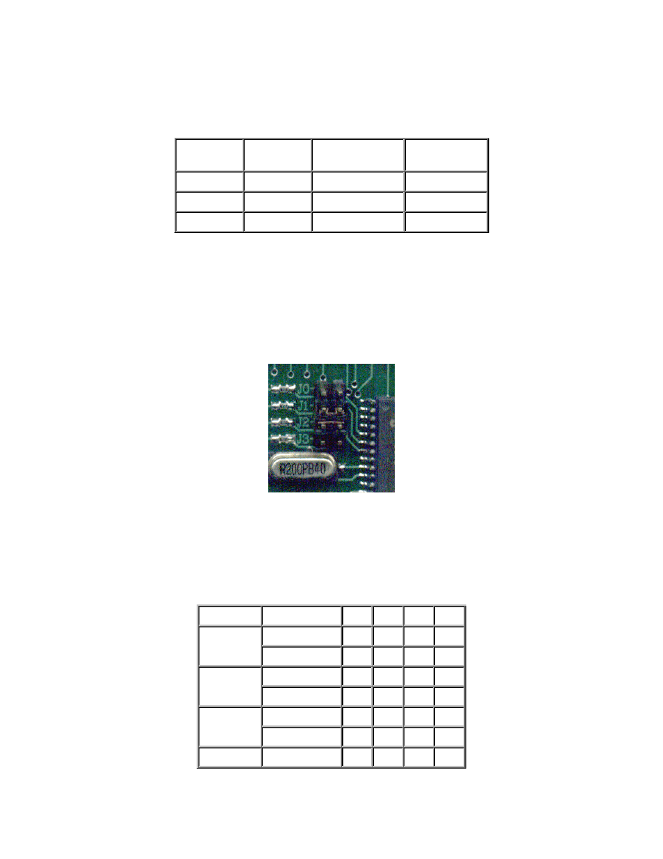
Figure 2-8 RS-232 jumpers
The module is supplied with jumpers J1 and J2 installed, which gives a RS-232 baud rate of 19200 and an
I
2
C address of 0x5C.
RS-232 port: J0, J1, J2 - control baud rate. RS-232 format is 8N1 (8 bits, no parity, one stop bit)
I²C port: J0, J1, J2, J3 - sets slave peripheral address
Baud Rate
Slave Address
J3
J2
J1
J0
50H
out out out out
1200
52H
out out out in
54H out
out
in
out
2400
56H out
out
in
in
58H
out in out out
9600
5AH
out in out in
5CH out
in
in
out