2 power/data connector, 3 protocol select jumpers – Matrix Orbital LK204-25 Legacy User Manual
Page 14
2.2
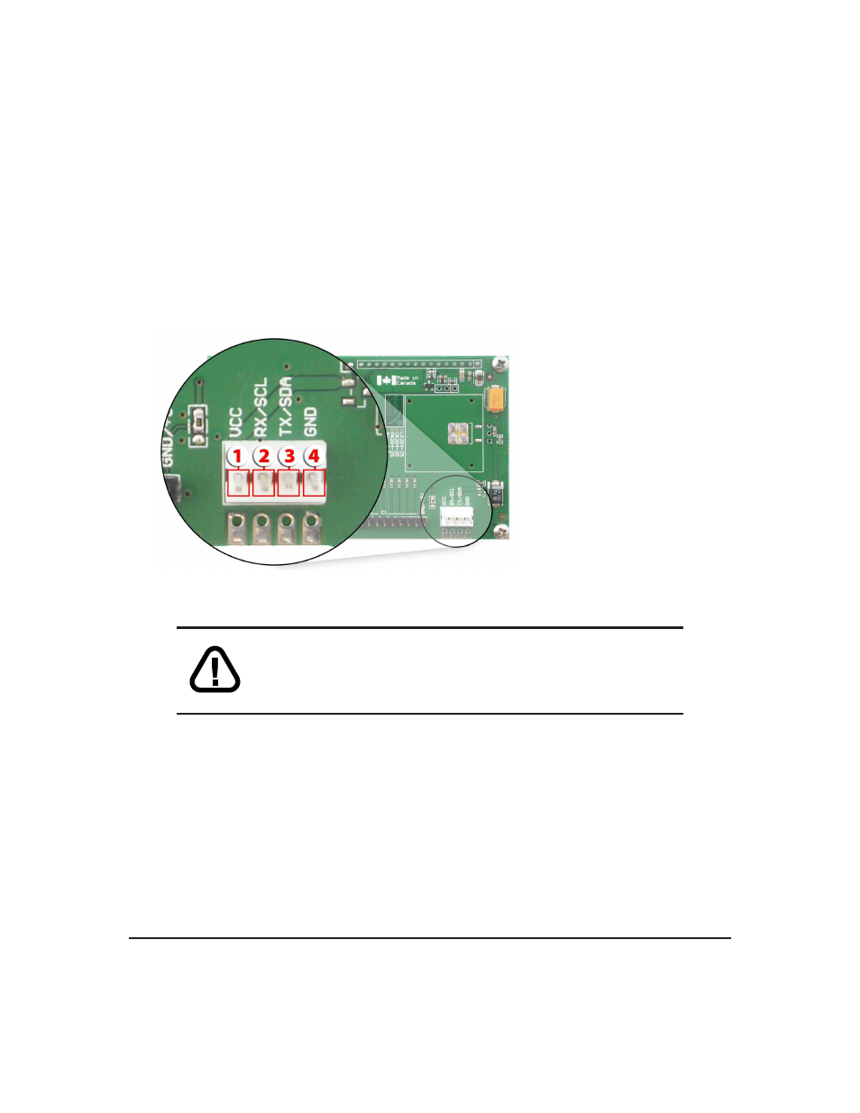
Power/Data Connector
The Power/Data Connector provides a standard connector for powering the display module. The LK204-
25 requires five volts for the standard display module, between nine to fifteen for the wide voltage (V)
and between nine to thirty-five volts for the wide voltage with efficient power supply module (VPT). The
voltage is applied through pins one and four of the four pin Power/Data connector. Pins two and three are
reserved for serial transmission, using either the RS-232/TTL or the I
2
C protocol, depending on what has
been selected by the Protocol Select Jumpers.
Pin
1
PWR
(See table 70 on page 54)
Pin
2
Rx \ SCL (I
2
C clock)
Pin
3
Tx \ SDA (I
2
C data)
Pin
4
GND
Figure 16: Power Connector and Pin out
WARNINGS
• Do not apply any power with reversed polarization.
• Do not apply any voltage other than the specified voltage.
2.3
Protocol Select Jumpers
The Protocol Select Jumpers, pictured below in
figure 17
, provide the means necessary to toggle the
display module between RS-232, TTL and I
2
C protocols. As a default, the jumpers are set to RS-232 mode
with solder jumps on the 232 jumpers. In order to place the display module in I
2
C mode you must first
remove the solder jumps from the 232 jumpers and then place them on the I2C jumpers. The display will
now be in I
2
C mode and have a default slave address of 0x50 unless it has been changed. Similarly, in order
to change the display to TTL mode, simply remove the zero ohm resistors from the 232 or I
2
C jumpers and
solder them to the TTL jumpers.
Matrix Orbital
LK204-25
10