Ashcroft PT-N7 - Temperature Switches User Manual
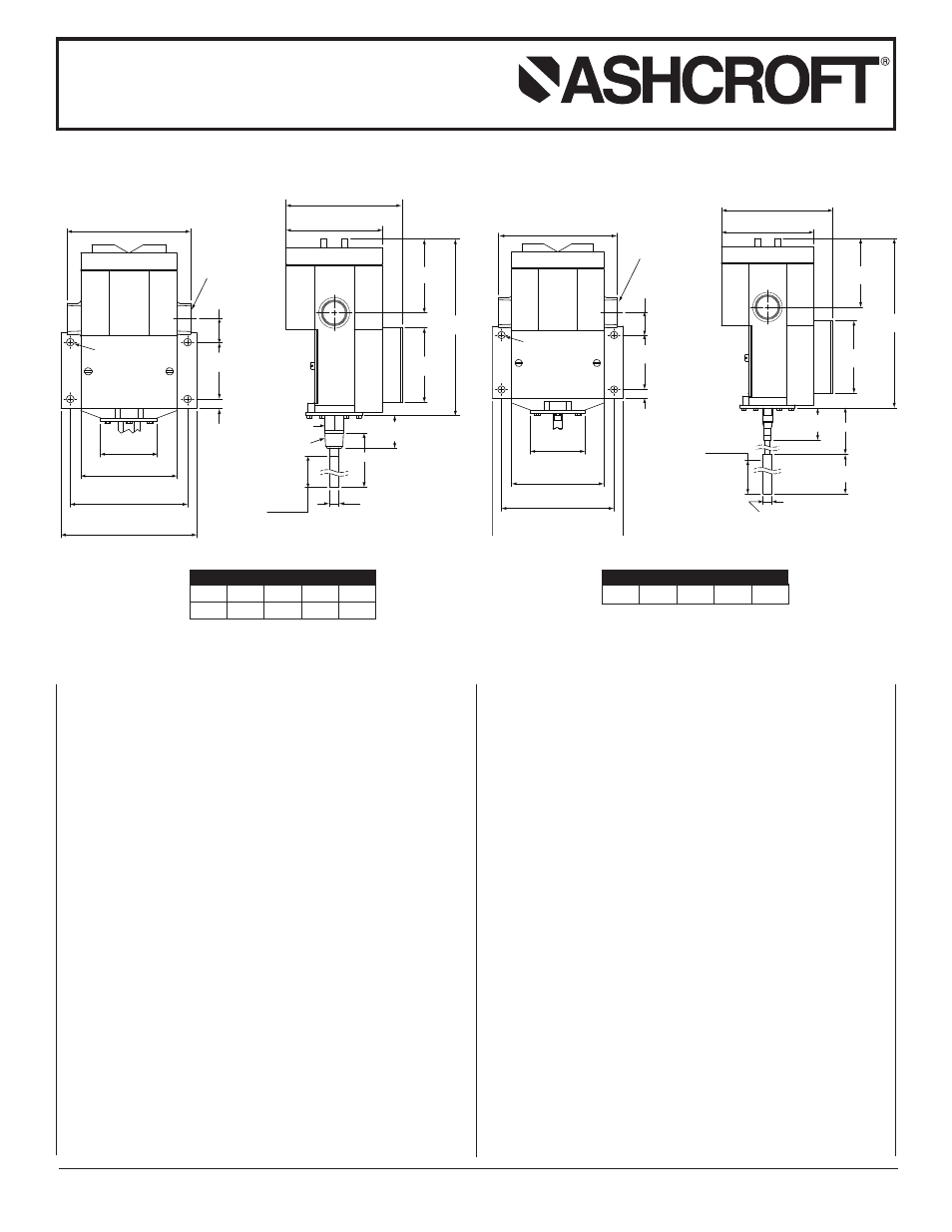
Direct mount remote mount
I
nstallation and Maintenance Instructions for
ASHCROFT
®
P-Series Snap Action
Switches for Temperature Control
INTRODUCTION
The Ashcroft temperature control is a precision device which
features a snap action switch. Fixed deadband is available with
single or dual SPDT independently adjustable switches with
various electrical ratings. Adjustable deadband is available with
a SPDT switch with various electrical ratings. Bulb material is
stainless steel.
The “P” Series Ashcroft snap action pressure switch is available
in both standard NEMA-4 and explosion-proof NEMA 7 & 9 con-
figurations. The enclosure is an epoxy coated aluminum casting.
INSTALLATION
This control is a precision instrument and should never be left
with internal components exposed. During installation insure that
covers are in place and conduit openings are sealed.
Good piping practice requires the use of a well for installation
where pressure may be applied to the thermal system, for pro-
tection against physical damage as well as corrosive effects of
media flow. Use of a well also facilitates removal of the bulb
from the process line without disturbing the process. Standard
well materials include brass,, steel, and stainless steel; other
materials are available on application. Selection should be based
on corrosion resistance requirements and process pressure.
MOUNTING
Four holes in the bracket supplied are used in surface
mounting of the control. Location of these holes is shown on the
general dimension drawings. An optional pipe mounting bracket
is also available. Mount on a vibration free surface or pipe.
A. STEM MOUNTED CONTROLS
These controls have a
1
⁄
2
NPT threaded adapter and may be
attached directly (or indirectly by means of a thermowell) to
equipment to be controlled. WHEN INSTALLING OR
REMOVING CONTROL ALWAYS USE THE WRENCH
FLATS OR HEX ABOVE THE THREADS. DO NOT TWIST
THE HOUSING.
B. REMOTE MOUNTED CONTROLS
Two types of union bushings are available to install a remote-
mounted control bulb into a thermowell or other
1
⁄
2
NPT thread-
ed hole. A non-pressure-tight type consists of a bushing, split
grommet and compression nut. To use this, the bulb is insert-
ed through the nut and the split grommet is slipped onto the
capillary between the compression nut, and the bushing.
After positioning the bulb as desired, tighten the compression
nut to the bushing. This will lock the capillary at the desired
location. The pressure-tight type is clamped to the bulb after
insertion by tightening a compression nut. To use this, the
union bushing is screwed into the
1
⁄
2
NPT threaded hole. The
compression nut and sleeve are slipped onto the bulb which
is then inserted into the union bushing. Bulb is then posi-
tioned and compression nut is hand tightened plus 2
1
⁄
4
turns.
This will lock the bulb at the desired location.
1.06
(27)
2.30
(58)
0.38
(10)
4.75
(121)
3.88
(99)
5.50
(140)
5.00
(1 2
7 )
Ø 0.3 1X 4 HOLES
(8 )
Ø 2.3 1
(5 9 )
3/4 NPT
TYP
2.3 1
(59 )
ACTIVE
LENGTH
Ø 3. 90
(9 9 )
4. 7 0
(1 1 9 )
3. 0 6
(7 8
)
2. 9 0
(7 4 )
7. 1 6
(1 8 2 )
2.5 0
(6 4 ) “L”
3.0 0
(7 6 )
Ø 0 . 3 7
(9)
BULB
1.06
(27)
2.30
(58)
0.38
(10)
4.75
(121)
3.88
(99)
5.50
(140)
5.0 0
(1 2
7 )
Ø 0.31 X 4 HOLES
(8 )
Ø 2. 31
(59 )
3/4 NPT
TYP
Ø 3 .
90
(99 )
4.7 0
(119 )
3. 06
(7 8
)
2. 90
(7 4
)
7. 16
(1 8
2 )
“S”
Ø 0.3 7(9 )
2. 3 1
(5 9 )
ACTIVE
LENGTH
1 /
2 NPT
7 /
8 HEX
1. 31
MALE
BULB
(33)
N4 – 5.8 lb. (2.6)
N7 – 6.4 lb. (2.9)
N4 – 6.8 lb. (3.1)
N7 – 7.4 lb. (3.4)
Direct Mount
Remote Mount
2
3
⁄
4
4
6
9
12
(70)
(102)
(152)
(229)
(305)
STEM LENGTH (S)
IN.
MM
© 2007 Ashcroft Inc., 250 East Main Street, Stratford, CT 06614-5145, USA, Tel: 203-378-8281, Fax: 203-385-0499, www.ashcroft.com
All sales subject to standard terms and conditions of sale. I&M009-10012-10/00 (250-2551) AMR 12/07
5
10
15
20
25
LINE LENGTH
FT.