Ashcroft EL - Industrial Bimetal Thermometer User Manual
Installation, Method of selecting the set, Type 91 series adapter kit
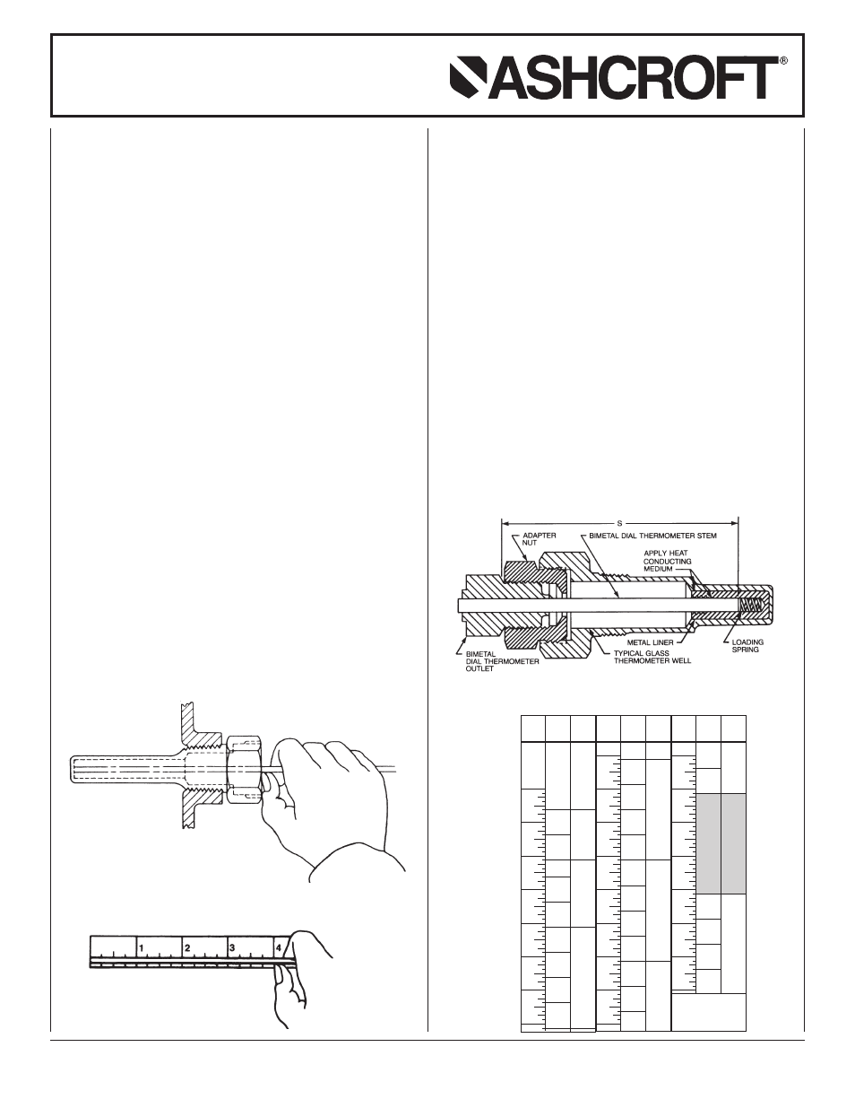
INSTALLATION
Assemble the adapter nut into the well and tighten se-
curely. (See Figure 3.)
Before installing the Bimetal Dial Thermometer into the
adapter and well, coat the lower 3˝ section of the ther-
mometer with a layer of heat conducting medium. This
will improve the temperature response of the ther-
mometer.
The metal liner is then slipped over the end of the
thermometer stem and a coating of heat conducting
medium is applied to the outside wall of the liner.
The thermometer and the liner are then inserted into
the well and tightened in position. Do not tighten more
than is necessary to prevent the thermometer from
turning.
Where service temperatures exceed 350°F the heat
conducting medium may smoke when first subjected
to a high temperature. This is caused by the vehicle, in
the heat conducting medium, vaporizing and leaving
the dry solids behind. This should not be cause for
alarm. The dry solids will act equally well as a heat
conducting medium for temperatures up to 1000°F.
The Type 91 Series Adapter Sets were designed to
provide a simple means of installing a bimetal dial
thermometer into an existing industrial glass ther-
mometer well.
The adapter set consists of:
1. A metal liner and spring assembly.
2. An adapter nut.
3. A small supply of heat conducting medium.
METHOD OF SELECTING THE SET
The Adapter Sets are available in four different sizes,
to cover various depths of wells. The “Selection Chart”
shows the Adapter Set number and the Bimetal Dial
Thermometer stem length to use for any well depth
from 3
5
⁄
8
˝ up to 25
1
⁄
8
.˝
To select the proper Adapter Set and Bimetal Dial
Thermometer stem length, measure first the well
depth by inserting a pencil, or any small diameter rod
or stiff wire until it reaches the bottom. (See Figure 1.)
Be sure the rod does not hang up on any shoulder in-
side the well. Using your thumb as an index, withdraw
the rod and measure the distance from the end of the
rod to the index point. (See Figure 2.)
Then use the chart to select the Adapter Set and the
Bimetal Dial Thermometer stem length to fit the well.
Note that one stem length of thermometer covers several
different well depths by using the correct Adapter Set.
For example, a thermometer with a 9˝ long stem can
be used for well depths between 7
1
⁄
8
˝ and 10
1
⁄
8
,˝ by
choosing the correct Adapter Set.
The liner is tapped with a
5
⁄
16
-
˝ 18 machine thread so it
can be removed from the well if desired.
Figure 1
Figure 2
WELL
STEM
DEPTH
ADAPTER
LENGTH
IN
SET NO.
“S”
INCHES
3
4
91B
4
91A
5
91C
6
91B
6
91A
7
91D
8
91C
9
9
91B
91A
10
WELL
STEM
DEPTH
ADAPTER
LENGTH
IN
SET NO.
“S”
INCHES
10
91D
11
91C
12
12
91B
91A
13
91D
14
91C
15
15
91B
91A
16
91D
17
18
91C
18
WELL
STEM
DEPTH
ADAPTER
LENGTH
IN
SET NO.
“S”
INCHES
18
91B
18
91A
19
20
21
22
91D
23
91C
24
24
91B
91A
25
Figure 3
SELECTION CHART
Note: If the measured well
depth falls on the dividing line
between two stem lengths
and/or two Adapter Sets choose
the stem and/or Adapter Set
above the line.
INSTALLATION AND MAINTENANCE
INSTRUCTIONS FOR ASHCROFT
®
TYPE 91 SERIES ADAPTER KIT
© 2011 Ashcroft Inc., 250 East. Main Street, Stratford, CT 06614-5145, USA Tel: 203-378-8281, Fax: 203-385-0499, www.ashcroft.com
All sales subject to standard terms and conditions of sale. I&M008-10004K-03/11