MagTek Excella STX99875344 User Manual
Page 2
Page 2 of 4
Page 3 of 4
Device Address Setup
• Using My Computer go to the folder C:\program files\Magtek\Excella-STX.
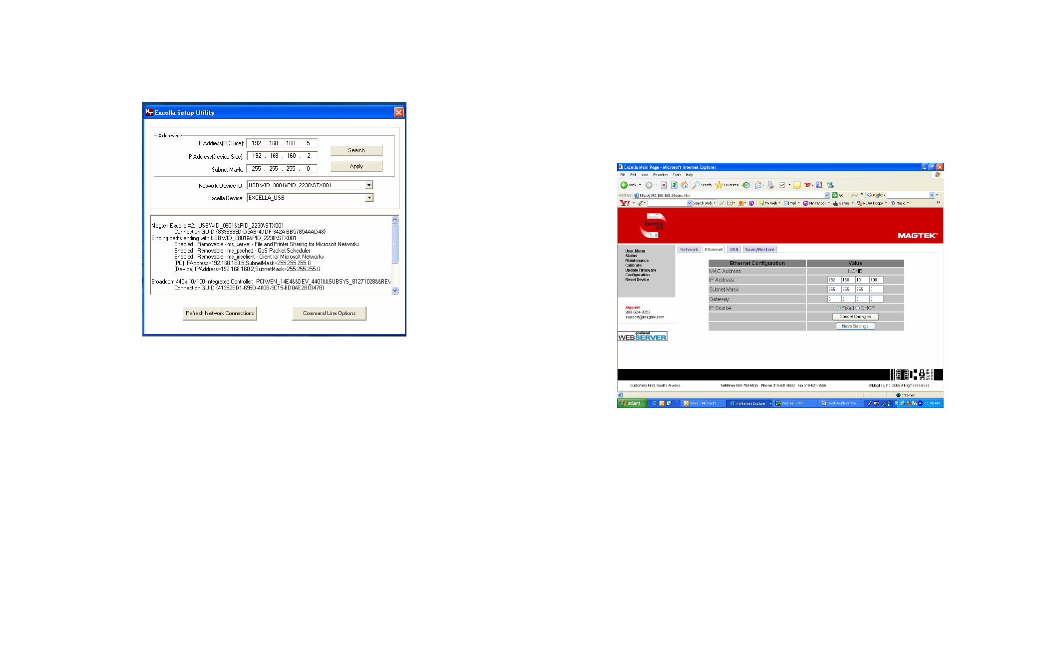
• Run the ExcellaUSBConfig.exe program (see Figure 2 below)
Figure 2. Excella Setup Utility Screen
• For Subnet Mask, Network Device ID and Excella Device, accept the defaults shown.
• Click once on the Search button (this will automatically fill in valid IP addresses).
• Click on the Apply button.
• Click OK.
• Close this program.
• Continue to Step 4, INSTALL INK CARTRIDGE(S) below.
3. ETHERNET INSTALLATION
Connect cables
• Connect Ethernet interface cable, USB to Excella STX (refer to Figure 1 above).
• Connect round connector from the power supply to Excella.
• Connect the power cord to the socket on the power supply block.
• Connect the three-prong power cord to AC wall outlet.
• Wait until only the middle LED is illuminated with a steady green.
• Connect interface cable to PC.
Ethernet Configuration
• In your web browser, type Excella STX’s default Ethernet IP address as follows: http://192.168.10.100;
Excella STX’s built-in web page will be displayed.
• In the User Menu, click on Configuration.
• Select the Ethernet tab and configure all parameters shown (see Figure 3 below).
• Click on Save Settings and close the web browser.
• Continue to Step 4, INSTALL INK CARTRIDGE(S) below.
Figure 3. Ethernet Configuration Screen
4. INSTALL INK CARTRIDGE(S)
• Remove the outer cover by pressing the release buttons on each side and lifting the cover.
• Remove the center cover by pressing the rear/front release buttons and lifting the cover.
• Ensure the printer latch is down and locate the alignment pegs on the Printer/Cartridge and the guide
holes in the Printer Base (see Figure 4 below).
• Slide the alignment pegs into the guide holes as indicated in the figure below.
• Raise the latch so that it touches the Printer/Cartridge.
• Press the latch into the lock position, and move the Cartridge slightly to ensure it is locked.
• If needed, perform steps 1-4 on the Front Printer/Cartridge located inside of the exit path.
Figure 4. Rear Print Cartridge Installation/Removal