Burr King Model 720 User Manual
Page 8
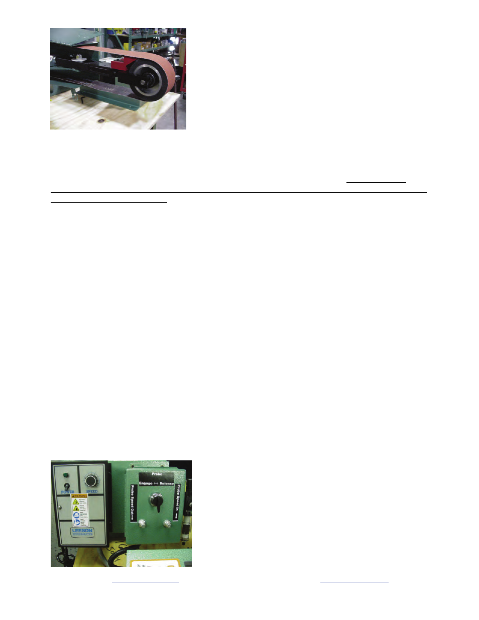
Picture 2: Note red pinch guard. Note guard door is open, do not operate the machine with the guard door open.
8. Insure that the grinder is located in an area that provides clear access to the machine such that operators
have clear and unobstructed access to the machine. The work place should be free from floor obstructions,
trip points, and other faults that may reduce operator safety.
9. Burr King recommends that all three phase installations include a magnetic starter. Magnetic starters
protect motors from “single phasing”, overheating, etc. thereby reducing the risk of damage to the equipment
and/or fire hazard to your facility.
10. Insure that the model 720 AC power source is properly sized, and properly fused. You should consult a
competent electrician, or you may call Burr King Manufacturing for guidance.
Functional operating instructions for the model 720 belt grinder
The model 720 was fully tested and verified to comply with requirements prior to shipping from the factory.
You should perform the following steps:
1. Securely bolt the machine to a table, pedestal, or other \mounting location. The base of the model 720
has 4 mounting holes for this purpose. Use grade 5 or better bolts for mounting the machine. If the
machine is mounted with the motor shaft other than horizontal use 5/16 bolts or larger. otherwise use ¼
inch or larger bolts.
2. If the machine controls and air regulator assembly is console mounted securely mount the console in a
convenient location where the operator can access the controls WITHOUT REACHING OVER THE
MACHINE. Operating the controls while reaching over the machine may lead to serious bodily
injury.
3. Insure that the regulator assembly is mounted such that the bowls are vertical.
4. Connect a clean air pressure source of at least 45 PSI to the air pressure regulator supplied with the
model 720.
5. Note the air controls that are mounted either in the base of the model 720 or in an attached console. The
function of each control is described by control labeling ( see picture 3). With these controls you can
retract the front wheel to remove and install abrasive belts, adjust the speed of probe extension, and
adjust the speed of probe retraction. Ordinarily you will not need to adjust the latter two controls.
CAUTION: The abrasive belt to wheel interface will close quickly so KEEP CLEAR OF THESE
INTEFACES WHEN OPERATING THE AIR CONTROLS. NEVER OPERATE THE AIR
CONTROLS WHILE THE ABRASIVE BELT IS IN MOTION. FAILURE TO FOLLOW THESE
INSTRUCTIONS MAY LEAD TO BODILY INJURY.
See our catalog at
www.burrking.com
Contact
us
at
DOC720OP-99 REV10/02
2