Auxiliary equipment, Operating parameters – Allstar Products Group 3500 User Manual
Page 16
16
D:
AUXILIARY EQUIPMENT
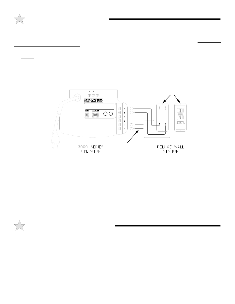
INSTALLATION OF DELUXE WALL STATION
The Allstar Plus Deluxe Wall Station is an optional accessory designed to work with any Allstar 3000 Series Operator. Connection
to any other operator may damage the operator and/or Wall Station. Only connect one operator to each Wall Station. Do not connect
more than one Wall Station to an Operator.
STEP 1:
After determining a suitable location, usually near the access door And at least 5 feet above the floor to prevent use by
children, use the Wall Station as a guide to mark the mounting holes. Drill holes for drywall anchors or screws. NOTE: Do not
mount directly to masonry walls. Use backer board.
STEP 2:
A length of 4-conductor, #22 gauge wire is required to connect the Wall Station to the garage door operator. Strip
approximately 6” of the wire jacket from one end and 1/2” of insulation from each wire. Carefully connect one wire to each of
the four terminals indicated, noting which color is connected to which terminal. Tighten screws, being careful that no wires are
allowed to touch any other terminal or any other conductive part of the circuit board. Do not overtighten the terminal screws.
STEP 3:
Push the wire jacket into one of the four notches provided at the ends of the housing, allowing a maximum of 1/8” inch of
the jacket inside the case (too much will make mounting difficult). Carefully tuck the loose wires into the case and mount the unit
using the screws provided.
STEP 4:
Run the wire from the Wall Station to the operator, supporting it at 18” intervals with suitable staples. Leave a sufficient
length to make the necessary connections to the operator terminal strip.
WARNING: SOME LOCAL BUILDING CODES DO NOT ALLOW SURFACE WIRING. BE SAFE AND
CHECK WITH YOUR LOCAL BUILDING INSPECTOR FIRST.
STEP 5:
Disconnect the power from the operator. Strip approximately 8” of jacket from the end of the wire and 1/2” insulation
from each wire. Connect to terminals 0, 1, 4 and 5 as shown in the illustration above. Support the wire near the operator with
wire ties.
STEP 6:
Reconnect power to the operator and test the Deluxe Wall Station functions as described in the Operation and Adjustment
Instructions.
Please note the following Operating Parameters which apply to Openers with Auxiliary Entrapment Protection System connected.
(All-Clear Photosystem, Installation Instructions on Page 13.)
IF THE DOOR IS...
...FULLY OPEN, then pushing the standard wall Push Button will cause the door to begin MOVING DOWNWARD.
...FULLY CLOSED, then pushing the wall Push Button will cause the door to begin MOVING UPWARD.
...STOPPED, PARTIALLY OPEN, then pushing the wall Push Button will cause the door to begin MOVING UPWARD.
...MOVING UPWARD, then pushing the wall Push Button will cause the door to STOP.
...MOVING DOWNWARD, then pushing the wall Push Button will cause the door to STOP, PAUSE FOR APPROXIMATELY
ONE SECOND, AND THEN BEGIN MOVING UPWARD.
E:
OPERATING PARAMETERS
4-CONDUCTOR
22 GAUGE WIRE
MOUNTING
HOLES
BACK
FRONT
104389