Installing the epson printer interface, Interface connection details – rs485 – Videoswitch Vi-POSIF-S User Manual
Page 4
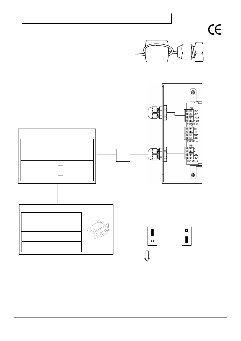
Installing the Epson printer interface
Installing the Epson printer interface
Vi-POSIF-S
EPSON TM T 88 serial
SHEET 4-9
Interface Connection Details – RS485
Failure to install the ferrite sleeves on the power and data
cables as shown, will compromise the EMC performance
of this unit, relevant to the EMC directive 89/336/EEC.
RS485 data out P5
Pin 4
-
Black
Pin 3
+
Red
Pin 2
ground
White
Pin 1
-EN
LINK
ferrite
sleeve
ferrite
cable gland on
rear of interface
interface
route data cable through the respective ferrite and loop
through once again.
*IMPORTANT: cable must be looped through ferrite sleeve.
data out from P5 should be terminated with a
DB9 (Vi-POSCON)
Vi-POSCON
DB 9 (F)
DATA IN
Pin 4
RX+
Red
Pin 9
RX-
Black
Pin 5
ground
White
N.B. towards front of Vi-POSCON unit.
On Vi-POSCON pcb, enable the relevant RS485 input by moving
the corresponding jumper (P9 - P12) per input channel (1-4)
i.e. from ;
to ;