2 - led connections – HighPoint RocketRAID 2340 User Manual
Page 12
RocketRAID 2340 Hardware Description/Installation
2-2
Speaker (“BEEP1”)
Alarm: the speaker emits an audible alarm in the case of disk/array failure.
JP3
This jumper is used to enable and disable the card’s alarm (BEEP1). The default
position is enabled (1, 2).
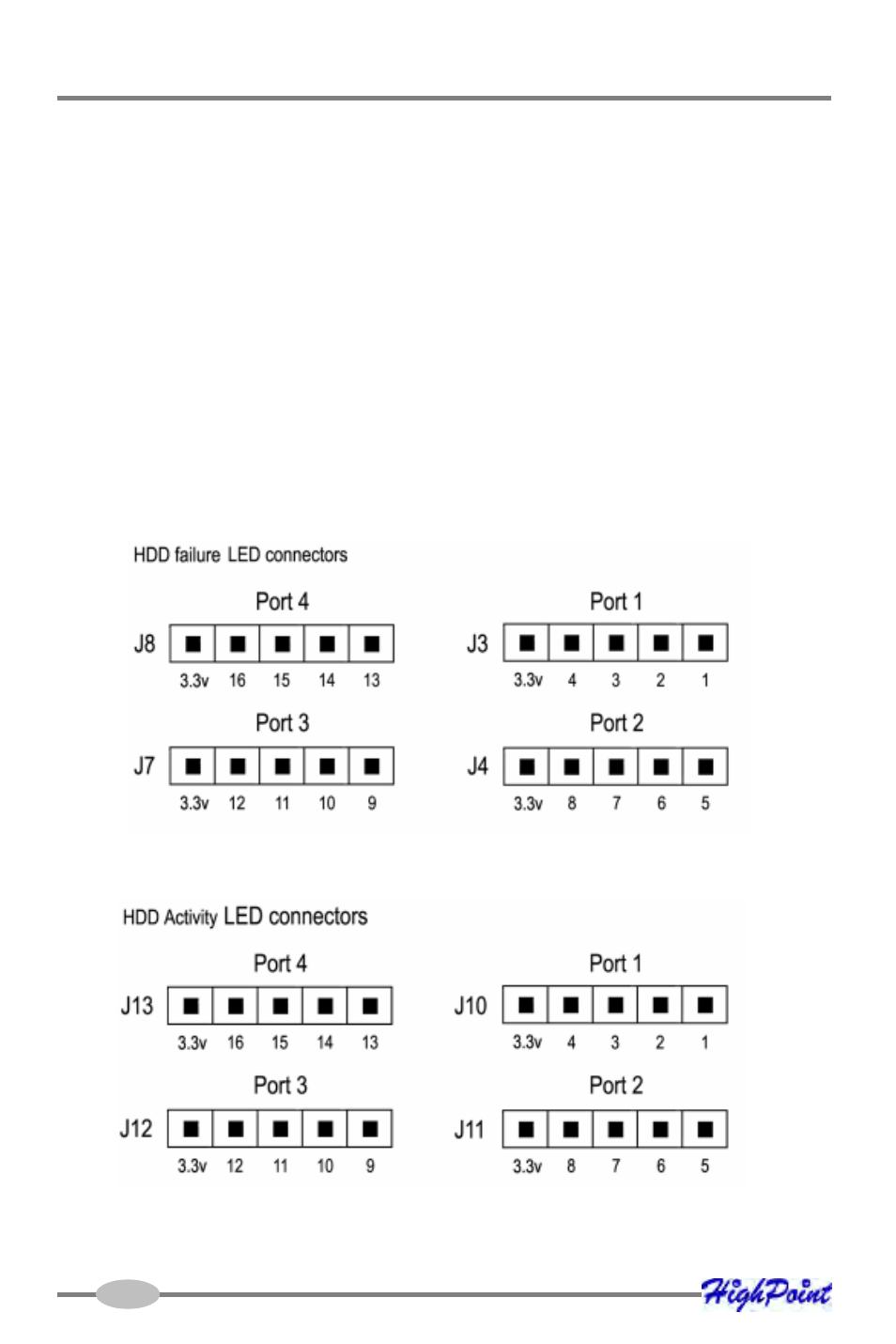
2 - LED Connections
The numbered pins represent each SATA channel (1-16). The term “Port” refers to the
RocketRAID 2340’s Mini-SAS connectors.
Connectors J11-13 provide hard disk activity LED support.
Connectors J3, J4, J7 and J8 provide hard disk failure LED support.
See also other documents in the category HighPoint Power suppliers:
- RocketStor 6328 (40 pages)
- NA762TB (12 pages)
- NA762TB (41 pages)
- NA381TB (3 pages)
- NA333TB (3 pages)
- NA211TB-LD (3 pages)
- RocketRAID 4520 (8 pages)
- RocketRAID 2720C2 (19 pages)
- Rocket 2722 (8 pages)
- RocketRAID 2782 (60 pages)
- RocketRAID 2760 (60 pages)
- RocketRAID 2744 (65 pages)
- RocketRAID 2722 (23 pages)
- RocketRAID 4322 (60 pages)
- RocketRAID 4460 (59 pages)
- RocketRAID 2684 (35 pages)
- RocketRAID 2644X4 (84 pages)
- RocketRAID 2642 (35 pages)
- RocketRAID 362x (8 pages)
- RocketRAID 640L (8 pages)
- Rocket 640L (8 pages)
- RocketRAID 622 (8 pages)
- RocketHybrid 1220 (43 pages)
- RocketRAID 3560 (62 pages)
- RocketRAID 3520 (80 pages)
- RocketRAID 2522 (90 pages)
- RocketRAID 2322 (73 pages)
- RocketRAID 2320 (77 pages)
- RocketRAID 2314 (92 pages)
- RocketRAID 2310 (75 pages)
- RocketRAID 2302 (81 pages)
- RocketRAID 2300 (81 pages)
- RocketRAID 2240 (72 pages)
- RocketRAID 2224 (54 pages)
- RocketRAID 2220 (46 pages)
- RocketRAID 2210 (99 pages)
- RocketRAID 1742 (65 pages)
- RocketRAID 1720 (71 pages)
- Rocket 622 (8 pages)
- RocketRAID 644 (7 pages)
- RocketStor 5422A (2 pages)
- RocketStor 5411A (2 pages)
- RocketStor 5422 (8 pages)
- RocketStor 5122B (29 pages)