And o-ring – Vaisala WAA151 User Manual
Page 13
Chapter 3 __________________________________________________ Installation
VAISALA__________________________________________________________11
For installation, follow the procedure below:
1.
Remove the four screws holding the cover of the
junction box. Remove the cover.
2.
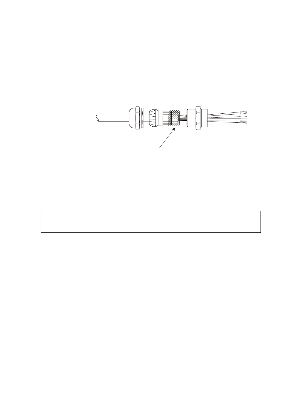
Lead the power and signal cables through the cable
gland(s). For better protection against RF interference,
bend the cable shield as illustrated in Figure 4 below.
0206-046
Figure 4
Cable Shield Bent over the Plastic Sleeve
and O-ring
3.
Connect the wires to the screw terminal block inside
the junction box according to the appropriate wiring
diagram provided in section Connections on page 13.
Finally, tighten the output cable gland(s) properly.
NOTE
The wiring diagram inside the box is applicable only for
WAA151 and WAV151 sensors with the shaft heating.
4.
Carefully reattach the enclosure cover with the four
screws. Make sure that the gasket seals the junction
box properly.
5.
Attach the cross arm to the top of a pole mast with the
mounting clamp, refer to Figure 5 on page 12. Align
the cross arm as instructed in section Alignment on
page 15 before erecting the mast.