Wiring, Important - read before installation – Vaisala GMP231 User Manual
Page 2
1
5
6
7
3
4
8
2
Wiring
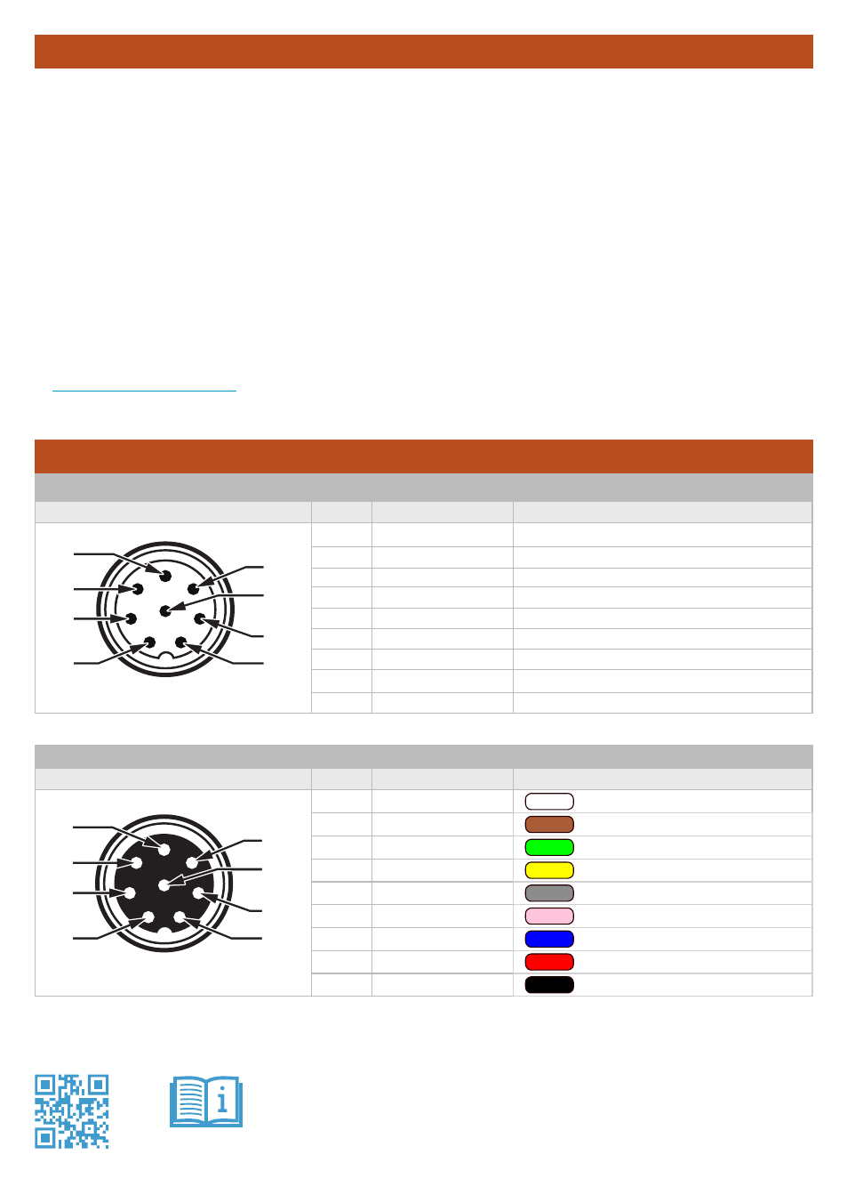
GMP231 Connector Pinout
Male 8-pin M12
Pin #
Function
Note
1
I
2
C SDA
Three-wire 5 V I
2
C (pins 1, 3, and 8).
2
RS-485 D-
RS-485 default setting: 19200, 8, N, 1.
3
I
2
C SCL
4
Analog output +
0 ... 20 mA or 4 ... 20 mA output.
5
Standby
Ground this pin to turn off measurement.
6
RS-485 D+
7
Power supply +
11 ... 30 VDC, max. 1 W (pulsed).
8
Ground
-
Shield
Connect shield on both ends of cable.
© Vaisala 2014. All Rights Reserved.
Ref. M211603EN-B
Vaisala Oyj
Vanha Nurmijärventie 21
FI-01670 Vantaa, Finland
*M211603EN*
www.vaisala.com/gmp231
1
6
8
7
3
4
5
2
Cable DRW240977
Female 8-pin M12
Pin #
Function
Open ended wires (no connector)
1
I
2
C SDA
White
2
RS-485 D-
Brown
3
I
2
C SCL
Green
4
Analog output +
Yellow
5
Standby
Grey
6
RS-485 D+
Pink
7
Power supply +
Blue
8
Ground
Red
-
Shield
Black
GMP231 is designed to remain installed during typical heat sterilization cycles (maximum temperature inside
chamber 195 °C / 383 °F). To achieve this, you must install and operate the probe correctly:
•
Only the sensor should be exposed to heat. The filter must be completely in the heated chamber, but
the probe must remain inside the unheated chamber wall. The probe body must not extend more than
5 mm into the chamber.
•
During the sterilization cycle, you must turn off the CO
2
measurement, or power off the probe
completely.
•
The installation tube must be sealed from the chamber side to limit heat conduction, and to prevent
CO
2
in the chamber from entering the probe. Vaisala recommends a 44 mm diameter installation tube
together with Vaisala’s silicone plug.
For more information, download the complete GMP231 User’s Guide (document code M211501EN) from
www.vaisala.com/gmp231
.
Important - Read Before Installation