Electrical connections – Vaisala HMD60 User Manual
Page 2
HMD60U/Y
Operating Manual
HMD60U/Y-M210276en-A
2
2003-01-22
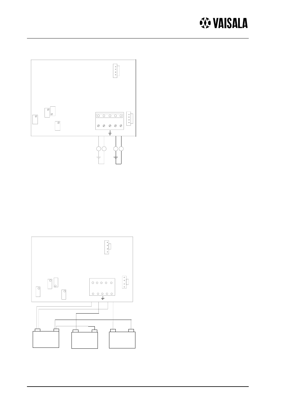
ELECTRICAL CONNECTIONS
Signal cables are connected to a removeable 5-pole screw connector. Make the
connections according to Figure 3a above. RH test and T test connectors are used with the
HMI41 or HM70 indicator equipped with an appropriate probe and optional calibration
cable.
Figure 3b shows the same connections in alternative way.
T GAIN
RH GAIN
RH OFFSET
T
OFFSET
RH
TEST
T
TEST
1 2 3 4 5
+
RH
-
RH
+
T
-
T
POWER SUPPLY
CHART RECORDER
AMMETER
OR CONTROLLER
CHART RECORDER
AMMETER
OR CONTROLLER
TEMPERATURE
10...35 VDC
+
+
------------
RH
+
------------
------------
-RH
+T
+RH
-T
T G A IN
R H G A IN
R H O FF S E T
T O F F S E T
T
T E S T
1
2
3
4
5
m A
+
T E S T
R H
m A
-
m A
mA
+
-
or
or
Figure 3a. Electrical
connections.
Figure 3b. Electrical
connections.
- Calibration of Digital Transmitters with HMI41 (36 pages)
- Calibration of Series HMDW2030 and HMP130 Transmitter with HMI41 (14 pages)
- Calibration of Series HMDW6070 and HMP140 Transmitter with HMI41 (30 pages)
- HM34 (30 pages)
- HM40 (47 pages)
- HM44 (52 pages)
- HM70 (83 pages)
- HMD40 (1 page)
- HMD70 (18 pages)
- HMDW110 (62 pages)
- HMDW80 (51 pages)
- HMI41 (74 pages)
- HMP41 (72 pages)
- HMK15 (39 pages)
- HMM100 (71 pages)
- HMM105 (23 pages)
- HMM211 (42 pages)
- HMM212 (36 pages)
- HMM213 (52 pages)
- HMP140 (28 pages)
- HMP155 (84 pages)
- HMP228 (115 pages)
- HMP230 (163 pages)
- HMP240 (130 pages)
- HMP260 (118 pages)
- HMP60 (71 pages)
- HMT100 (52 pages)
- HMT120 (87 pages)
- HMT130 (95 pages)
- HMT140 (76 pages)
- HMT310 (88 pages)
- HMT310 (105 pages)
- HMT330 (209 pages)
- HMT360 (97 pages)
- HMT360 (63 pages)
- HMT360N (110 pages)
- HMW40 (1 page)
- HMW90 (110 pages)
- SHM40 (68 pages)
- RDP100 (14 pages)