State GS6 75 XRRS User Manual
Page 13
13
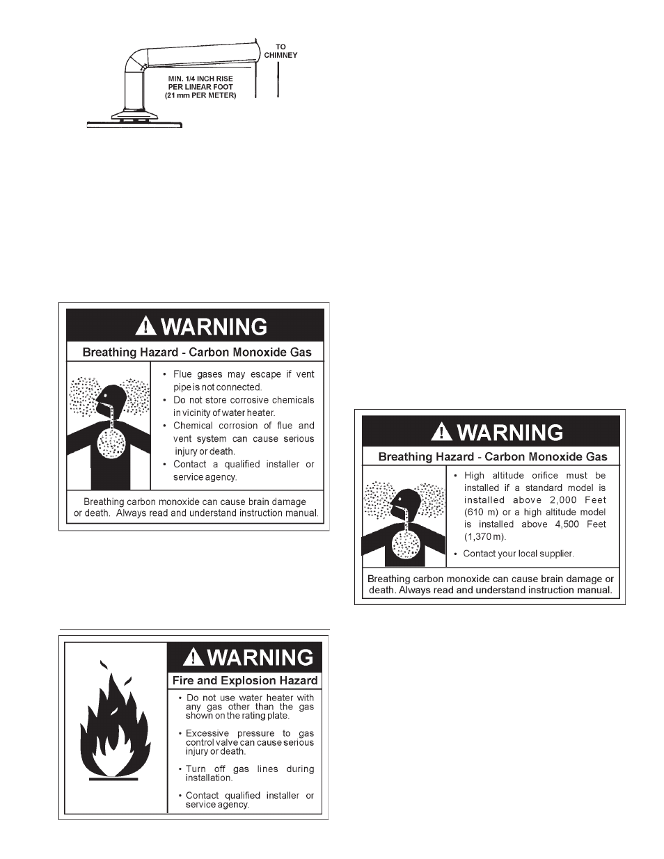
FIGURE 12.
There must be a minimum of 6” (153 mm) clearance between single
wall vent pipe and any combustible material. Fill and seal any clearance
between single wall vent pipe and combustible material with mortar
mix, cement, or other noncombustible substance. For other than single
wall, follow vent pipe manufacturer’s clearance specifications. To
insure a tight fit of the vent pipe in a brick chimney, seal around the vent
pipe with mortar mix cement.
Failure to have required clearances between vent piping and combustible
material will result in a fire hazard.
Be sure vent pipe is properly connected to prevent escape of dangerous
flue gases which could cause deadly asphyxiation.
Chemical vapor corrosion of the flue and vent system may occur if air
for combustion contains certain chemical vapors. Spray can
propellants, cleaning solvents, refrigerator and air conditioner
refrigerants, swimming pool chemicals, calcium and sodium chloride,
waxes, bleach and process chemicals are typical compounds which
are potentially corrosive.
GAS PIPING
Make sure the gas supplied is the same type listed on the model rating
plate. The inlet gas pressure must not exceed 14 inch water column
(2.6 kPa) for natural and propane (L.P.) gas. The minimum inlet gas
pressure shown on the rating plate is that which will permit firing at
rated input.
If the gas control valve is subjected to pressures exceeding 1/2 pound
per square inch (3.5 kPa), the damage to the gas control valve could
result in a fire or explosion from leaking gas.
If the main gas line shut-off serving all gas appliances is used, also turn
“off” the gas at each appliance. Leave all gas appliances shut “off”
until the water heater installation is complete.
A gas line of sufficient size must be run to the water heater. Consult
the current edition of National Fuel Gas Code ANSI Z223.1/NFPA 54 and
your gas supplier concerning pipe size.
There must be:
•
A readily accessible manual shut off valve in the gas supply line
serving the water heater, and
•
A drip leg (sediment trap) ahead of the gas control valve to help
prevent dirt and foreign materials from entering the gas control
valve.
•
A flexible gas connector or a ground joint union between the shut
off valve and control valve to permit servicing of the unit.
Be sure to check all the gas piping for leaks before lighting the water
heater. Use a soapy water solution, not a match or open flame. Rinse
off soapy solution and wipe dry.
The minimum inlet gas pressure shown on the rating plate is that which
will permit firing at the rated input.
Standard Models are for installation up to 2,000 feet (610 m) above
sea level.
High Altitude models are for installation from 2,000 feet
(610 m) to 4,500 feet (1,370 m) above sea level.
If a standard model is installed above 2,000 feet (610 m) or high altitude
model is installed above 4,500 feet (1,370 m), the input rating should be
reduced at the rate of 4 percent for each 1000 feet (305 m) above sea
level which requires replacement of the burner orifice in accordance
with National Fuel Gas Code ANSI Z223.1/NFPA 54 or Contact your
local gas supplier for further information.
Failure to replace the standard orifice with a high altitude orifice when
installed at elevations above 2,000 feet (610 m) or above 4,500 feet
(1,370 m) for high altitude model could result in improper and inefficient
operation of the appliance, producing carbon monoxide gas in excess
of safe limits, which could result in serious injury or death. Contact
your local gas supplier for any specific changes which may be
required in your area.