Locating the new water heater (cont’d) – State PR6 75 XRPDT User Manual
Page 9
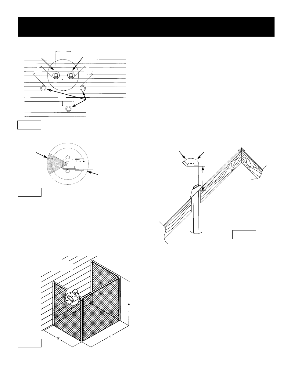
Must maintain
adequate service
and maintenance
accessibility.
Range of degrees
available for vent
pipe installation.
Figure 5
Figure 7
Locating the New Water Heater (cont’d)
9
Figure 6
Air for Ventilation for
Appliances Located in Confined
Spaces
Air for ventilation should be provided if installed in a confined
space. Refer to the National Fuel Gas Code, ANSI Z223.1.
Figure 4
WIRE FENCE
When the water heater outlet terminal is low enough to be
touched accidentally, or is accessible to small children, a
wire mesh chain link fence (as shown in Figure 6) may be
used. Care should be taken to maintain adequate ventila-
tion around the outlet terminal. If a chain link fence is
installed, it must not be used as a storage area for items that
may block proper ventilation.
NOT TO BE USED AS
A STORAGE AREA
Venting Through Roof – Clearances
•
0
″ clearance for 3″ PVC, ABS, or CPVC Schedule 40 piping
from combustible and noncombustible surfaces.
•
The vent exhaust outlet and air inlet terminals shall terminate at
least 18 inches above the roof surface. Figure 7.
•
The venting system must be installed in a manner which
allows inspection of the installation of the venting pipes and
joints as well as periodic inspection after installation as
required by ANSI Standards.
VENT PIPE SEPARATION
The inlet and outlet vent pipes must be separated by a min-
imum distance of 6 1/2 inches up to 24 inches maximum.
18
″
24
″
NATURAL DRAFT (GRAVITY)
DIRECT VENT, POWER
VENT, OR POWER DIRECT
VENT APPLIANCE INLET
AND/OR OUTLET VENT(S).
VENT OUTLET
AIR INTAKE
18
″
6 1/2
″ MIN.
24
″ MAX.
18″
45°
45° VENT CAP
W/SCREEN
90° STREET ELL