State GS6 75 YRPDT User Manual
Page 20
20
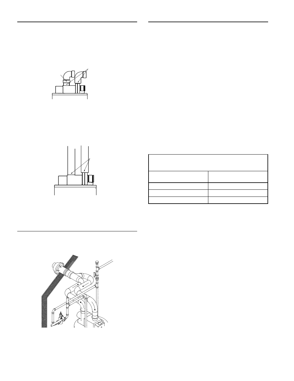
CONNECTING VENT TO BLOWER
1. If making an immediate horizontal run of vent off the blower, install
the following at the blower inlet: one 3" PVC Schedule 40 pipe
(3" long minimum) and one 3" PVC Schedule 40 elbow. At the
outlet, install one 3" PVC Schedule 40 street elbow. (Exception:
For the outlet, use CPVC for 75 gallon models and ABS for 50
gallon 65,000 Btu/Hr models.) Place the elbows in the required
direction on the blower, then secure as described in Figure 27.
A. SECURE BOTH THE
OUTLET ELBOW AND THE
INLET PIPE WITH 3
EVENLY SPACED SCREWS,
THEN CAULK JOINTS AT
BLOWER.
B. SECURE INLET ELBOW TO
INLET PIPE WITH
SOLVENT
CEMENT.
FIGURE 27.
2. If there is to be a vertical run of vent from the blower, the 3” PVC
inlet and the 3” PVC (CPVC for 75 gallon models and ABS for
50 gallon 65,000 Btu/Hr models) outlet pipes must be attached
to the blower and venting hood using 3 sheet metal screws
each.
SECURE EACH PIPE
WITH 3 EVENLY
SPACED SCREWS
CAULK JOINT
AT EACH PIPE
FIGURE 28.
INSTALLATION SHOWING USE OF (OPTIONAL)
CONCENTRIC TERMINATION KIT
Optional 3" PVC Horizontal Vent Kit
(Kit Number 9006475005):
FIGURE 29.
If this concentric termination, through the wall type of venting
system is preferred, the concentric vent kit can be ordered from
the Service Parts Department. Installation instructions are provided
with the kit.
VENTING THROUGH A ROOF
Two 3” inlet and outlet PVC Schedule 40 - 45° vent caps are supplied.
A 5’ (1.5 m) section of 3” CPVC Schedule 40 outlet vent pipe is
supplied with 75 gallon models and a 5’ (1.5 m) section of 3” ABS
Schedule 40 outlet vent pipe is supplied with 50 gallon 65,000 Btu/
Hr models. More may be required and must be purchased locally.
1. The water heater requires its own (separate) venting system.
2. Only 3" ABS Schedule 40 piping and fi ttings are acceptable
materials on the fi rst fi ve feet of the outlet vent system on the
50 gallon 65,000 BTU/HR models and 3" CPVC Schedule 40
piping and Schedule 80 fi ttings are acceptable materials on the
fi rst fi ve feet of the outlet vent system on 75 gallon models.
3. 3” PVC, ABS, or CPVC Schedule 40 piping and fi ttings are
acceptable materials for the inlet vent system and for the outlet
vent system after the fi rst fi ve feet (1.5 m).
4. The unit cannot be connected to existing vent piping or chimney.
5. Venting must terminate vertically to the outdoors.
6. The total vertical and horizontal vent runs cannot exceed the
maximum length with a maximum number of 90° elbows as
specifi ed in the table below. If more elbows are required, the
venting distance must be reduced 5 feet for every 90° elbow.
TABLE 2: The number of 90° elbows shown in the table is for both
the intake air and vent pipes. IE: The vent pipe can contain three 90°
elbows, the intake air pipe can also contain three 90° elbows.
3" DIA. VENTS MAX.
LENGTH (FT.)
NUMBER OF 90°
ELBOWS*
45
1
40
2
35
3
*NOTE: Two 45° elbows are equivalent to one 90° elbow. One 90°
elbow equals 5 feet (1.5 m) of equivalent vent length.