Ag Spray Equipment LA5000 Liquid Applicator User Manual
Page 5
3. Connect wiring harness if using hydraulic pump with rate
control.
4. Grease Applicator (Refer to Mainentance).
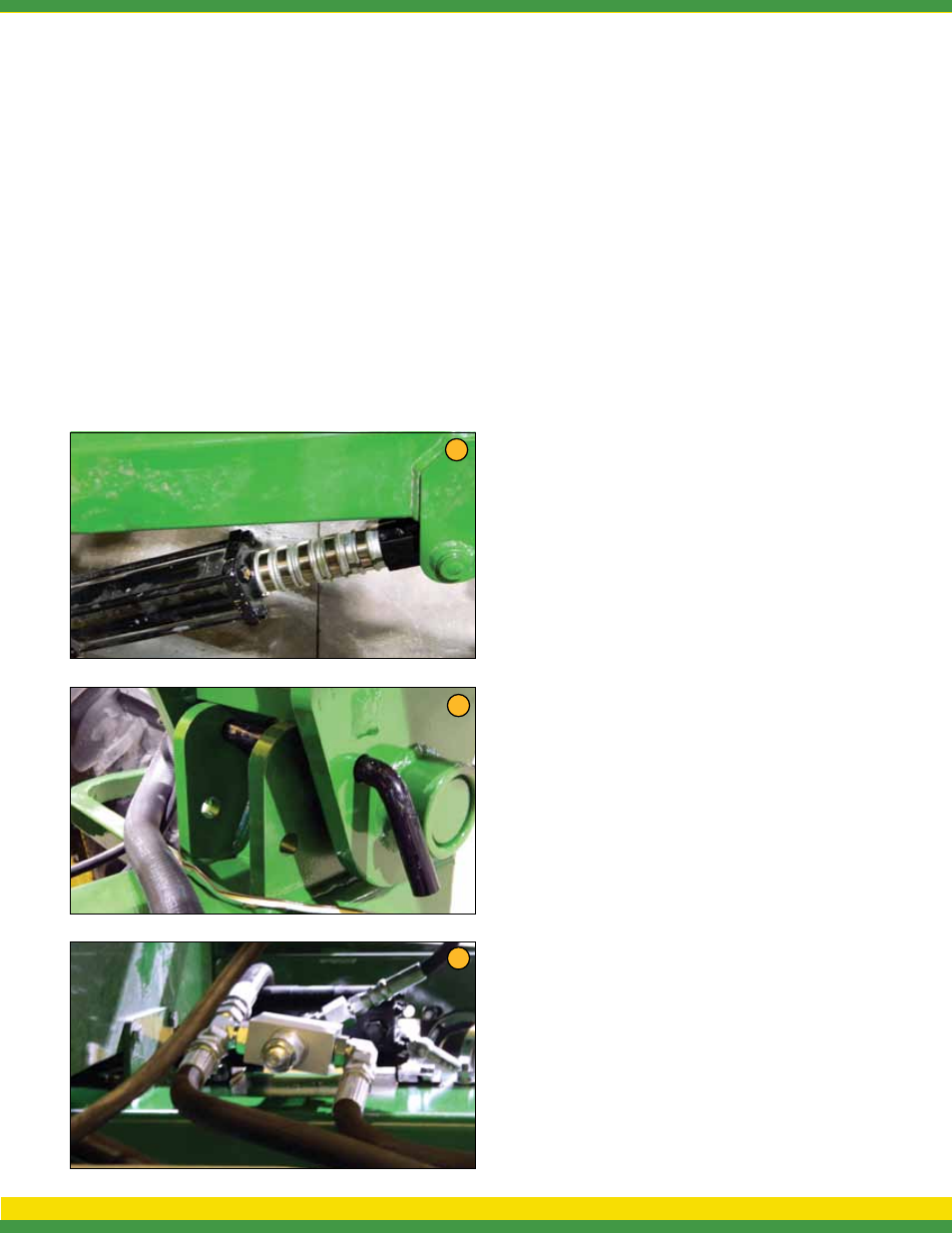
5. Before road travel, install all locking collars on toolbar
cylinders and safety pins on wings.
6. Remove locking collars as needed to maintain a depth of
4 to 5 inches. Constant down pressure on main lift is not
recommended (weight of toolbar will keep unit in the ground).
Leave hydrualic selector in neutral for field operation.
7. Remove safety pins on wing cylinders. Wing cylinders remote
will run in constant while down (Figure 7).
The Applicator is equipped with adjustable down pressure relief
valve on wing cylinders. The valve is preset at 800 PSI. This may
be adjusted as needed. The relief valve is located under tongue,
and requires an allen wrench to adjust (clockwise to increase
pressure and counterclockwise to decrease pressure.) (Figure 8).
8. After unfolding main wing, engage hydraulic lever in “constant
pressure.” This is necessary to allow wings to maintain
constant depth and follow uneven terrain, as well as the ability
to “gullwing” (Lift both wings evenly when turning. See #9).
9. Field Operation: When you come to the end of the field.
1. Lift main section
2. Pull back on main wing lever long enough to lift both
wings slightly (“gullwing”).
3. After turning, lower main section and wing section
and return wing hydraulics to constant pressure.
10. Check and clean screens as needed.
11. Pump Settings
Optional Ground Drive Pump
11a - Remove tranport pin
11b - Use John Blue pump setting slide chart. Loaded radius is
9.75 and sprocket ratio is 32 drive and 18 driven.
11c - Set pump to recommended setting.
Optional Hydraulic Drive Pump
a. Hydraulic pump hoses supplied on the applicator
include (1) 1/2” line and (1) 3/4” line. The 1/2” hose
is the hydraulic supply (in/pressure) and the 3/4”
hose is the return (out/non-pressure).
NOTE: It is recommended for optimal pump performance that
the 3/4” return line connect directly to the tractor hydraulic
reservoir (not tractor SCV port). Doing so eliminates possible
back pressure restriction on the 3/4” return line. Excessive
back pressure restriction can cause hydraulic orbital motor
damage/failure.
b. Proper hydraulic pump disengagement. When shutting off
the pump, move the selector to the FLOAT position to allow
the centrifugal pump to come to a gradual stop. Standard
spool valves, which are found on all tractor hydraulic systems,
can cause potentially damaging high peak pressures in the
hydraulic system when closed, because of abrupt shutoff of
oil flow in both the supply and return lines.
c. Close and lock down the bypass adjusting screw in the
hydraulic motor (if applicable).
Switch rate controller to manual and press the “+” button on
TeeJet or “Increase” button on Raven, hold for 8 seconds. Then
press the “-” button on TeeJet or “Decrease” button on Raven for
4 seconds.
Set the tractor hydraulic flow control valve for minimum hydraulic
oil flow to the remote outlet (Tortoise position).
Start the tractor and allow the hydraulic oil to circulate for
approximately 10 to 15 minutes or until adequately warmed.
Prime the centrifugal pump with all valves open.
Open the sprayer control regulating valve and the boom shut-off
valves.
Slowly adjust the tractor hydraulic flow control valve until the
desired boom pressure is attained.
NOTE: See manufacture pump operators manual for further
setup and maintenance.
7
6
8
A G S P R A Y . C O M 4