Sheet 2 side 2, Hub 10.3, Stacking (subphase master) – Outback Power Systems HUB10.3 - Quick Start Guide User Manual
Page 4: Three-phase stack (subphase master), Three-phase stack, Series stack (subphase master), Output, Ac b
Slave (A) Slave (A)
Master (A)
Subphase Master (C)
Slave (C)
Slave (C)
or
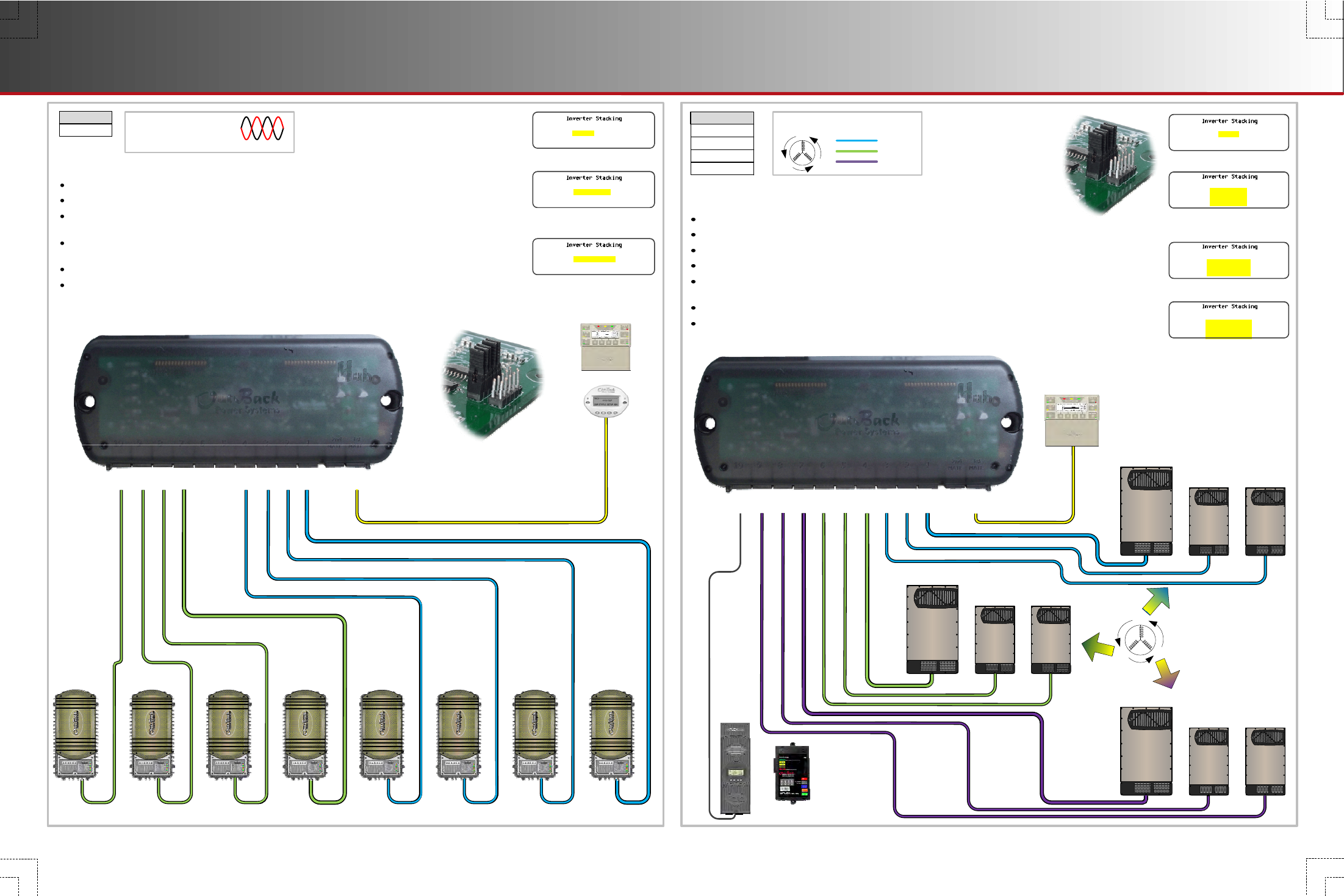
Three-Phase Stack (Subphase Master)
Up to 9 inverters (ports 1 to 9); 1 other device (port 10); MATE3 only
Master inverter (required on port 1) and up to two Slave inverters (ports 3 & 3) use Phase A output AC bus
Subphase Master inverter (required on port 4) and up to two Slaves (ports 5 & 6) use Phase B output AC bus
Subphase Master inverter (required on port 4) and up to two Slaves (ports 8 & 9) use Phase C output AC bus
Phase A, B, and C Slave inverters should be equal in number; Slave selection screen may display
Slave but
could display
OB Slave L1 depending on model
Master and Subphase Masters are always active; each type of Master regulates output based on its own load
Slave inverters remain in Power Save mode; the Master activates Phase A Slave inverters based on its load,
while the Subphase Masters
independently activate Phase B or C Slave inverters based on their own loads
Rev 002.013.000
or higher
Port 1
Stack Mode Master
Port 2
Stack Mode Slave
or
OB Slave L1
Port 4
Stack Mode B Phase Master
or
3p Classic B
Port 7
Stack Mode C Phase Master
or
3p Classic C
Also ports 3, 5, 6, 8, and 9
Three-Phase Stack
Up to 9 inverters; 1 other device (MATE or MATE3)
Subphase Master (B)
Slave (B)
Slave (B)
HUB 10.3
Stacking (Subphase Master)
HUB 10.3
900-0154-01-00 REV B.vsd\2014-03-03
©2013 OutBack Power Technologies. All Rights Reserved.
900-0154-01-00 REV B.vsd\2014-03-03
©2013 OutBack Power Technologies. All Rights Reserved.
GFX
Models
Series Stack (Subphase Master)
Up to 8 inverters (ports 1 to 4, 7 to 10); 2 other devices (ports 5, 6); No balancing transformer required
Master inverter and half of the Slave inverters use common output AC bus (L1); ports 2 to 4 are L1 slaves
Subphase Master inverter and half of the Slave inverters use a separate common AC bus (2); ports 8 to 10
are L2 Slave inverters despite the screen selection (OB Slave L1)
Port 7 is the L2 Subphase Master despite the screen selection (Classic Slave); this port is required
regardless of the number of Slave inverters
Master and Subphase Master are always active; each type of Master regulates output based on its own load
Slave inverters remain in Power Save mode; Master activates L1 Slave inverters based on its load, while the
Subphase Master
independently activates L2 Slave inverters based on its own load
Port 1
Stack Mode Master
Port 2
Stack Mode OB Slave L1
Also ports 3, 4, 8, 9, and 10
Port 7
Stack Mode Classic Slave
or
Single-phase
inverters:
Split-phase output
Output
10 9
8
7
6
5
4 3
2
1
X
1
st
MATE
Jumper position
(see step 4a
on front page)
Master (port 1 only)
Slave (port 2)
Subphase Master (port 7)
Stacking (Subphase Master)
GS7048E
GFX
GFX (E Series)
Models
GS3548E
A
C
B
Single-phase inverters:
Three-phase output
PHASE A
PHASE B
PHASE C
Output
Jumper position
(see step 4a
on front page)
Master (port 1 only)
Slave (port 2)
Subphase Master (port 7)
Subphase Master (port 4)
10
9 8
7
6
5
4
3
2
1
X
1
st
MATE
A
C
B
Slave (L2)
Slave (L2)
Slave (L2)
Subphase
Master (L2)
Slave (L1)
Slave (L1)
Slave (L1)
Master (L1)