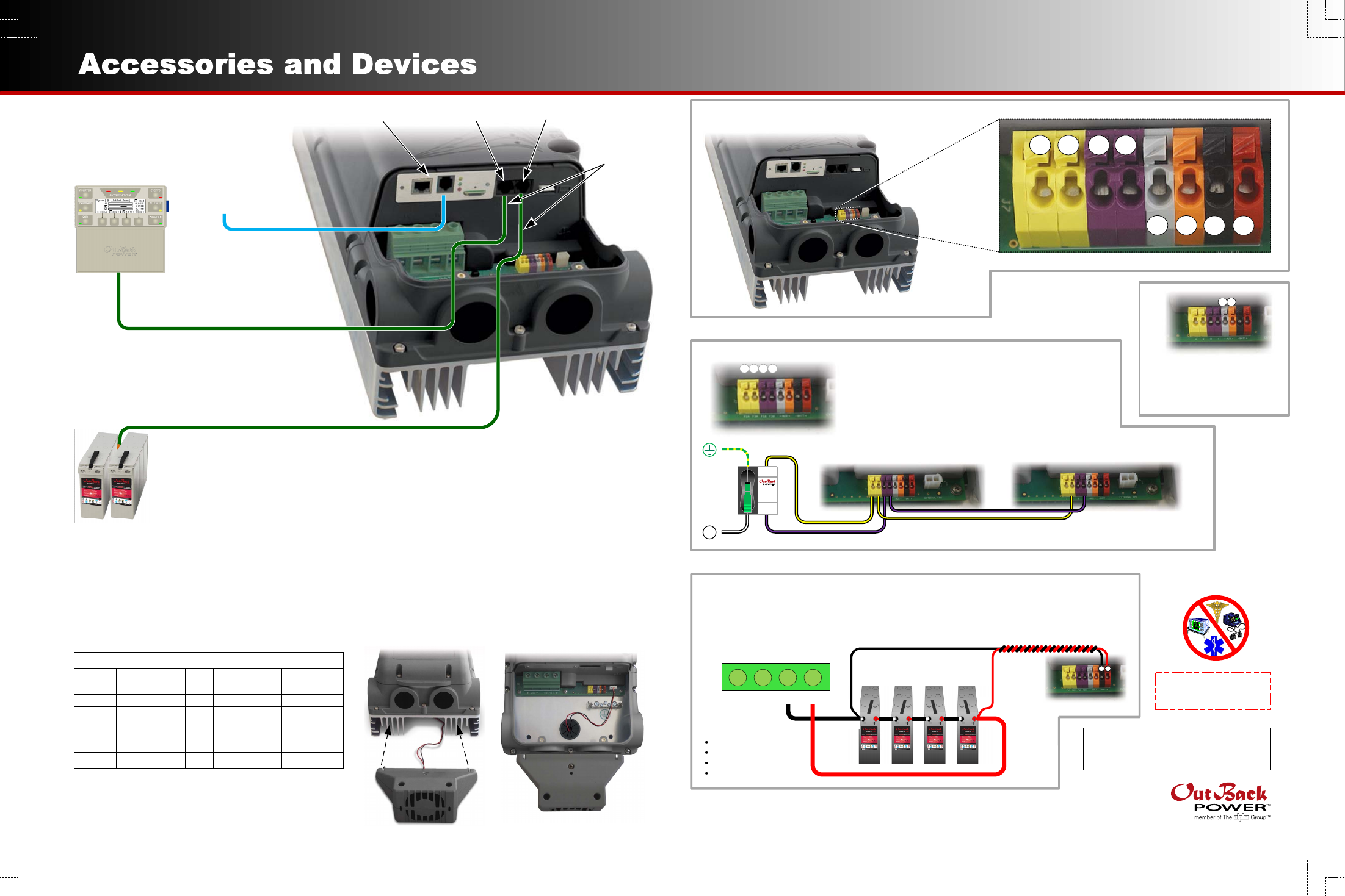
Flexmax extreme, Accessory terminal block ports and connectors, Mate3 system display and controller – Outback Power Systems FLEXmax Extreme Quick Start Guide User Manual
Page 2: Fan wiring, Fan mounting remote temperature sensor (rts), Battery sense terminals, Axs card mate3 rts
900-0151-01-00 Rev A.vsd\Accessories\2013-05-31
©2013 OutBack Power Technologies. All Rights Reserved.
FLEXmax Extreme
MATE3
System Display
and Controller
NOTE: See the FLEXmax Extreme
Owner’s Manual
for details on the settings
available in the main menu.
Accessory Terminal Block
Ports and Connectors
Fan Wiring
1 2
3 4
5 6 7 8
IMPORTANT:
Not intended for use with
life support equipment.
OutBack Power and the OutBack Power logo are trademarks owned and used by OutBack Power Technologies, Inc. The ALPHA logo and the
phrase “member of the Alpha Group” are trademarks owned and used by Alpha Technologies. These trademarks may be registered in the United
States and other countries.
Contact Technical Support:
Telephone:
+1.360.618.4363
Email:
Website:
www.outbackpower.com
Fan Mounting
Remote Temperature Sensor (RTS)
Battery performance changes when the temperature varies above or below room temperature
(77°F or 25°C). Temperature compensation is a process that adjusts charging to correct for these
changes. If not compensated, a battery may remain undercharged in cold temperatures and may
become overcharged when hot. Below room temperature, the charging set points are raised above
their normal values. Above room temperature the set points are lowered.
The RTS is attached to a single battery near the center of the bank. When charging, the RTS will
increase or decrease the charge voltage by a certain voltage per degree Celsius per battery cell.
The compensation value (the “slope”) is adjustable from 2 mV to 6 mV. Most batteries use a value
of 5 mV.
This setting affects the Absorbing and Float set points. Equalization is not compensated in the
FLEXmax Extreme.
Total compensation is determined by measuring the
number of degrees C above or below 25. This number
is multiplied by the number of 2-volt battery cells and
the slope value.
SunSpec Modbus
Interface
External Fault Terminals
(see page 1 for GFDI function)
GFDI or other shutdown functions can be used for multiple
controllers. Terminals 2 and 4 are wired to the next controller
as shown.
OFF
O
O
F
F
O
FAULT
PV
INACTIVE
NORMAL
PV ACTIVE
PV ARRAY
GROUND FAULT
DETECTOR
INTERRUPTER
Controller 1
Controller 2
1 2 3 4
GFDI
Battery Sense Terminals
These terminals monitor battery voltage more accurately than the main cable connections.
A twisted-pair cable is recommended. The connections are made directly on the battery
terminals.
NOTE: Overcurrent protection devices are not shown.
8
7
DC Terminals
PV+ PV- BAT- BAT+
Auxiliary (AUX)
Terminals
Used for diversion control
and other functions
6
5
Cells
(Volts)
Slope
Value Temp
25°C
±
Calculation
Vdc
Adjust
6 (12V)
5 mV
8°C
-17
6 x 0.005 x 17
+0.5 Vdc
12 (24V)
3 mV
36°C
+11
12 x 0.003 x 11
-0.4 Vdc
18 (36V)
5 mV
26°C
+1
18 x 0.005 x 1
-0.1 Vdc
24 (48V)
6 mV
0°C
-25
24 x 0.006 x 25
+3.6 Vdc
30 (60V)
2 mV
37°C
+12
30 x 0.002 x 12
-0.7 Vdc
Examples of Compensation
Install ferrite
clamps on
these cables
for EMI
suppression
AXS Card
MATE3
RTS
Recommended
protection for sense
conductors is:
Fast-acting device
80 Vdc or greater
1 A or smaller
Cold resistance
10 ohms or less