Outback Power Systems FLEXmax Extreme Quick Start Guide User Manual
Aflexmax extreme, Charge controller, Battery bank
900-0151-01-00 Rev A.vsd\Install\2013-05-31
©2013 OutBack Power Technologies. All Rights Reserved.
WARNING: Burn Hazard
The heat sink can become hot when the charge controller is operating.
Use caution when touching it during operation.
Dimensions
Height: 18.8" (47.1 cm); with fan 22.06" (56.0 cm)
Width: 8.8" (22.4 cm)
Depth to Wall: 6.0" (15.2 cm)
Mounting
The FLEXmax Extreme must be mounted upright at least 36" (91.4 cm)
above the ground or floor. Installation in shade is recommended.
Conduit hubs must be connected to the conduit before connecting to
the FLEXmax Extreme.
Clearance requirements are a minimum of 6“ (15.2 cm) above and
below the controller.
The unit can be mounted using either brackets (see A) or keyhole slots
(see B) on a secure mounting surface.
Name Color
Pattern
Bulk Abs Float EQ
Other
Off
Off
< 10 W PV available
Battery rest
Blue Solid
X
X
Blue
Flash long
X
Blue
Flash short
X
Float
Amber
Solid
X
X
≥ 1.91 Vpc
Green
Solid
X
Red
Solid
X
X
Battery discharge
<1.91 Vpc
Red
Flash
X
X
Critical batt discharge <1.75 Vpc
Amber/ Green
Flash
X
≤ EQ
Amber/ Red
Flash
X
Critical batt discharge <1.75 Vpc
AUX
Yellow
Solid
AUX active
Fault
Red
Solid
External Fault
N/A
Status
Any
N/A
LED Indicators (see wiring section)
Indicator
Controller State
Voltage
Charge
Included in Package
FM Extreme-150VDC
2 x Mounting Bracket
Silicone Grease Package
2 x Ferrite Clamp (install
on HUB/DEVICE and
RTS ports)
Provided by Customer
PV Array
Batteries
MATE3
Fan Kit
Disconnect Devices
Ground Fault Protection
Wiring & Cabling
Temperature
Range of ambient operating
temperature: -20°C to 45°C
(-4°F to 113°F)
Unit output derated above 45°C
(113°F)
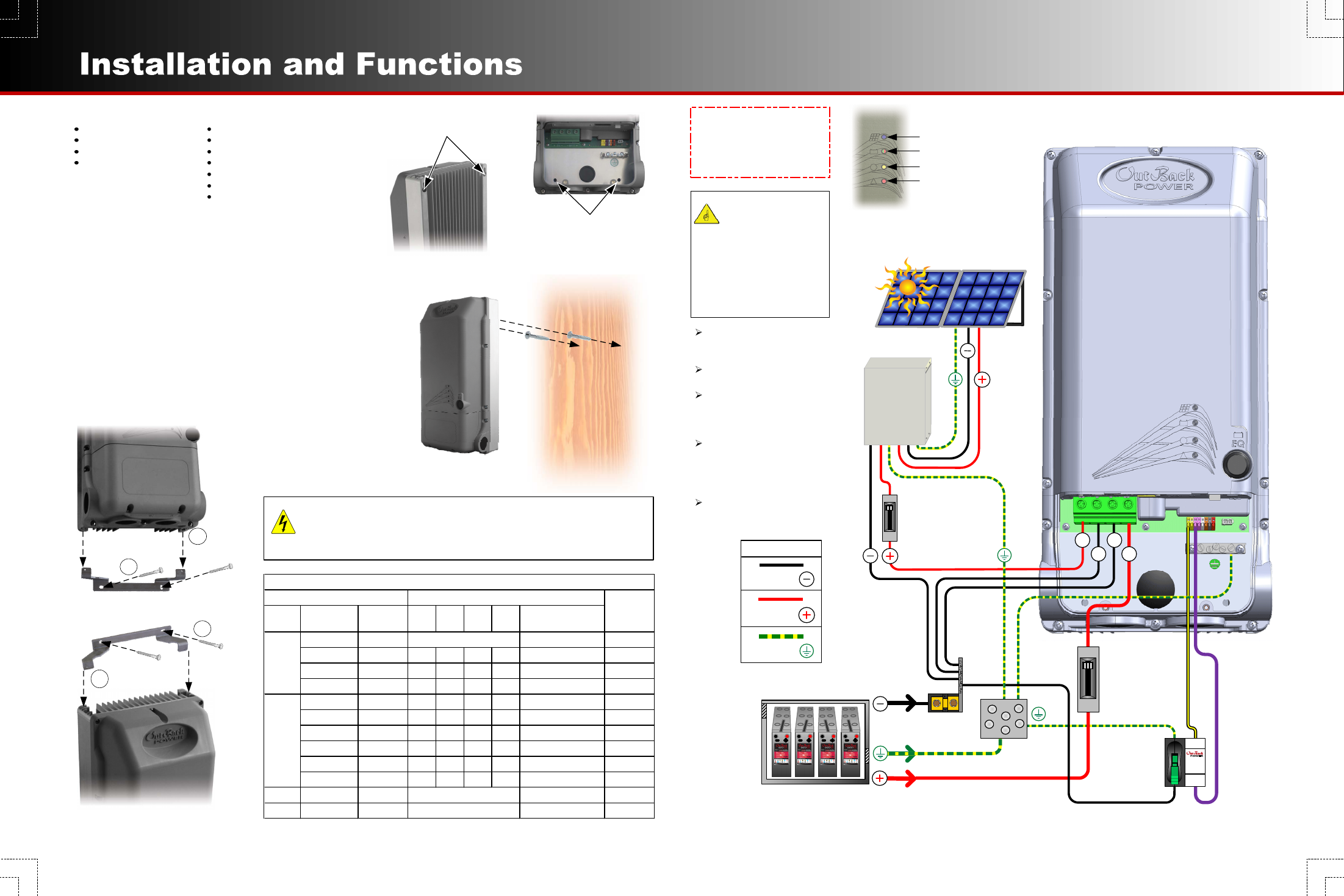
A
FLEXmax Extreme
Charge Controller
PV Combiner
Photovoltaic Array (PV)
Ground
Bus
Battery Bank
ON
OFF
BAT+
BAT–
PV–
PV+
Battery
Disconnect
(external)
Ground Fault Protection
(not provided, required by Article 690 of NEC)
Negative
Bus
ON
OFF
PV
Disconnect
(external)
Tighten all wire lugs and
ground terminals to 4 Nm
(35 in-lb) torque.
Use copper wiring only
(rated 90°C or higher).
Refer to the NEC and other
electrical codes for PV array
cable sizing, length, and
ampacity.
Use #4 AWG (25 mm
2
)
(minimum) for the controller
output terminals to the
batteries; output can accept
up to #2 AWG (35 mm
2
).
Negative-ground installation is
depicted here; positive
grounding is also permitted.
IMPORTANT: Example only.
Actual wiring may vary. All
configurations must comply with
local and national electric codes.
Consult your local electric authority
to ensure compliance.
Negative
Positive
Ground
DC LEGEND
IMPORTANT:
Wire sizes must
comply with local and
national codes. To
comply with the NEC,
input conductors and
circuit breakers must
be rated at 1.56 times
the short-circuit current
of the PV array.
OFF
O
O
F
F
O
FAULT
PV
INACTIVE
NORMAL
PV ACTIVE
PV ARRAY
GROUND FAULT
DETECTOR
INTERRUPTER
B
¼” hex head
lag screws
Keyhole Slots
(#14 slotted wood screws)
Securing Holes
(¼” hex head lag screws)
LED Indicators
(see above)
LED Indicators
Charging (Blue)
Status (Green/Red or Amber)
Auxiliary
Fault
NOTE: Overcurrent protection
for the battery circuit is to be
provided by installer.
Battery Nominal Voltages:
12-volt, 24-volt, 36-volt,48-volt, 60-volt
1
4
2
3