Maintenance – ATI Technologies Preseeder 365 User Manual
Page 25
19
MAINTENANCE
1. QD hub and Driven Sprocket mating sur-
faces must be clean and free of burrs.
2. Push the QD hub on until there is no side
play in the rotor.
3. Insert the bolts through the unthreaded
holes in the QD hub and into the threaded
holes in the Driven Sprocket. Tighten the
bolts evenly 1/2 turn at a time to 9 ft. - lbs.
torque
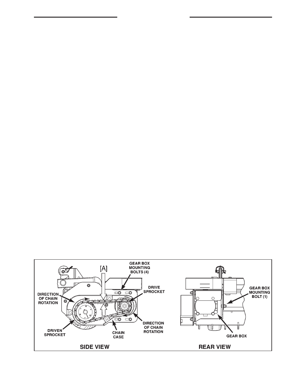
DRIVE CHAIN ADJUSTMENT
Check chain tension after the first 40 hours
of operation. Then check/adjust chain every 100
hours following initial adjustment. (See Figure
33.)
1. Turn off tractor engine and lower tiller
onto level ground.
2. Remove the three bolts (3), and access
closure.
3. Check slack of the chain. Measure [A]
midway between the sprockets on the top
side of the chain. If there is more than 3/4"
of slack adjust the chain. Release the main
drive belt. Loosen the mounting bolts (5)
for gear box, push the gear box mounting
assembly toward the Tractor [A], tighten
the mounting bolts. Then recheck slack.
5.Move the Adjustable Idler Pulley (A)
toward the Gearbox Pulley (B) (to shorten
the spring) or away from the Gearbox
Pulley (to lengthen the spring) as required.
6. Tighten the bolt in the center of the
Adjustable Idler Pulley (A).
7. Check belt tension by moving the Drive
Belt Release Handle to the engaged posi-
tion and measuring the spring length.
DRIVE CHAIN REMOVAL
1. Turn off tractor engine and lower tiller
onto level ground.
2. Remove the three bolts (3), and access
cover.
3. Remove the QD hub from the Driven
Sprocket by removing the bolts in the hub
and putting them in the threaded holes in
the hub. Turn each bolt 1/2 turn until the
hub is loose and can be removed.
4. Remove the Drive Chain from the Drive
Sprocket and remove the Driven Sprocket
and Drive Chain together.
Reverse order with the following notes to rein-
stall the chain.
FIGURE 33 Drive Chain Adjustment