MJM Yachts 36z Express User Manual
Page 33
CHAPTER 6
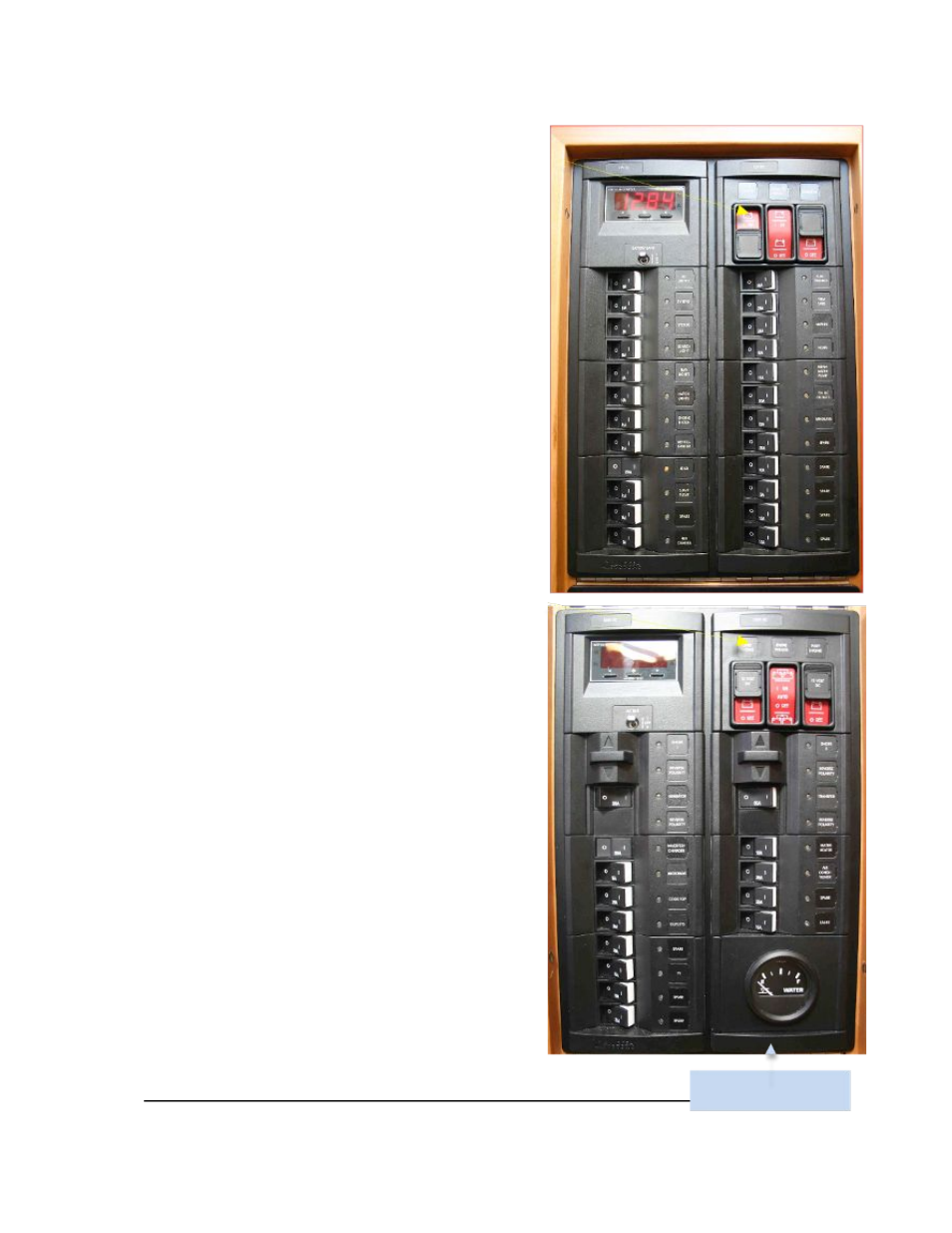
House and Generator battery switches
These rocker switches with sliding cover are located
on the upper right side of the DC panel with a Battery
Combiner between. When the battery combiner
switch is pushed DOWN, it is OFF. Pushed in UP it
is ON. It is recommended to leave it in the middle
AUTO position where it stays active at over 13.6 volts
and deactivates below 12.7 volts.
DC Breaker Panel This custom MJM panel Includes
digital readouts for voltage and amperage drain of the
House Bank in Position 1 of the display and reads
condition of the generator battery in Position 2.
To use DC components, the HOUSE battery bank
Rocker switch must be ON, the top main DC dis-
connect breaker on the panel must be ON,
and the component’s respective breaker must be ON.
Windlass Operation The windlasss uses Engine
Batteries, so it is necessary to have the Engine
Battery switches turned ON and ideally have the
engines operating when using the windlass.
The GENERATOR battery switch must remain on
when running.
Engine Battery Switches The two Engine Battery
Switches are located on the top right corner of the
AC Panel. To start the engines or use the windlass,
the engine START battery switches must remain
ON. The Combiner switch between, manually in the
UP position combines the two engine start batteries
should one of them fail. The DOWN position is OFF
and the MIDDLE position is AUTOMATIC combining
of the two engine batteries and also the house bank
if voltage is under 12.7 volts…deactivating when
over 13.7 volts.
6.2 AC PANEL
Breaker Panel The main AC disconnect breakers
for AC #1 and AC #2 are located in the middle of the
AC Panel. They must be ON for shore-power to
supply the boat’s AC power.
AC Shore 1 (left half) includes breakers for those
items which can be handled by the Mastervolt
Inverter. To use the inverter, (1) the house battery
selector switch must be ON and (2) the inverter
breaker on the AC panel must be ON. Refer to the
inverter/charger manual for more information.
When the Shore 1 shore-power cable is attached
and the Shore 1 select breaker is ON, Shore 1 will
supply AC power to AC Panel #1.
27
Freshwater Tank Level Guage
ELECTRICAL SYSTEM