MBRP S8120 User Manual
Page 3
S8120 © 06/12
PAGE 3 OF 4
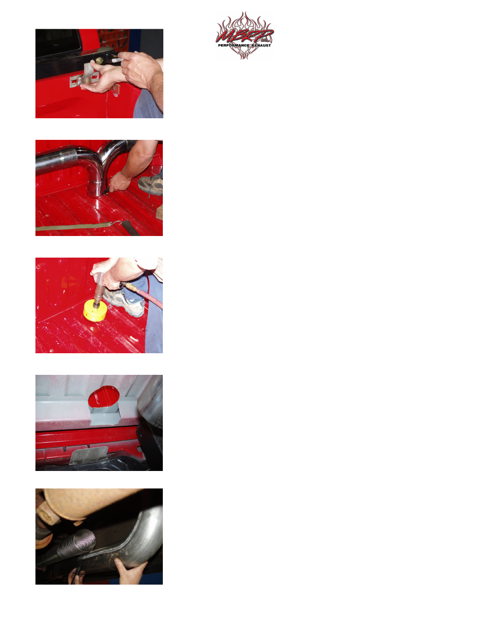
5. Place the Stack Mounting Brackets between each Stack and the front of
the truck bed so that the Stacks are properly spaced from the front of the
truck bed. Center the Stack Mounting Brackets on the Stacks and mark
the front of the truck bed in the center of the slotted holes in the Stack
Mounting Brackets. Center punch the marks and drill holes to
accommodate a 3/8” Bolt (included with the Stack Mounting Brackets).
Refer to Figure 5.
6. Loosely attach the Stack Mounting Brackets to the front of the truck bed
using the 3/8” hardware supplied. Set the Stacks up in the bed and loosely
attach them to the Stack Mounting Brackets. Make sure the Stacks are in
the desired position and the T-Pipe assembly is level.
7. Mark the bed floor where the T-Pipe is resting. MBRP Inc. recommends
tracing around where the T-Pipe meets the bed floor. Refer to Figure 6.
Remove the Stacks and T-Pipe assembly from the bed of the truck. Find
the center of the circle traced onto the bed floor, mark and center punch it.
Go under the vehicle and locate the center punch mark. This marks the
location where you are going to cut a hole for the T-Pipe to pass through
the bed of the truck. If you cannot find the center punch mark use a small
drill to create a pilot hole. Make sure that there is clearance for the 20”
Elbow to pass by any frame cross members. Remove or modify any heat
shields that there is interference with.
8. Cut a hole through the truck bed providing adequate clearance around the
part of the T-Pipe that passes through the truck bed. MBRP Inc.
recommends using a 5” diameter hole saw. It may be required to cut away
part of a bed rail. Refer to Figures 7 & 8.
9. Set the T-Pipe assembly at the desired height from the floor of the bed
(This will set the height of the Stacks). Using spacers to hold the T-Pipe at
the desired height, loosely attach the Stacks to the Stack Mounting
Brackets making sure that they are straight. This will hold the assembly
steady while you line up to the exhaust under the vehicle.
10. Measure from the T-Pipe slip joint to the Extension Pipe 40 5/8”. Add the
Extension Pipe 23” if installing on a Mega Cab. Mark and cut the shorter
side of the Elbow 20” to the required length so that it lines up with the
front part of the Extension Pipe. Refer to Figure 9. Note: if the system is
to long trim the length from the Extension Pipe or Pipes.
11. Attach the 20” Elbow to the T-Pipe slip joint and then attach the Flex
Pipe to both the 20” Elbow and the Extension Pipe. Refer to Figure 9.
Use the Clamps provided to secure the parts. The Hanger Clamp mounts
to the existing rubber isolator just after the Flex Pipe.
Figure 5
Figure 6
Figure 7
Figure 8
Figure 9