Manley LANGEVIN ALL-DISCRETE PULTEC EQP1-A TYPE EQUALIZER User Manual
Page 9
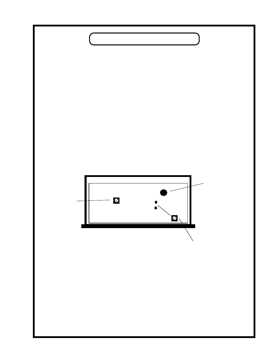
SERVICE NOTES
Location of
INTERNAL GAIN
ADJUST
CONTROL
FRONT OF CHASSIS
TOP VIEW
Location of
MAINS
VOLTAGE
CHANGE
SWITCH
45VDC
GND8
Location of
POWER SUPPLY
VOLTAGE
ADJUST and
TEST POINTS
POWER SUPPLY
There should be no reason to adjust this trimmer unless service to the power supply has taken
place. The procedure is to measure DC volts at the test points marked +45VDC and GROUND,
then adjust the trimmer for (you guessed it) 45 volts DC.
GAIN
The gain of the makeup amplifier is factory preset for unity gain from input to output in bypass
mode (which is also the same as all boost & cut controls set at minimum positions, fully
counter-clockwise). If for some reason your EQ needs to be re-trimmed for unity gain or you
need other than unity gain the trimmer is labelled VR1 and it adjusts the basic gain of the
output line amplifiers. To adjust this, simply remove the top cover by unscrewing the single
rear center fixing screw and sliding the top cover out towards the rear.
The pot is located in the center left third of the PCB. Adjustment should be made with
reference to a signal generator and external AC voltmeter.
It may be worth noting that there are separate discrete amplifiers for pins 2 and 3 on the XLR.
The input for the amp for pin 3 is derived from the signal on pin 2. The signal feeding the 1/4"
unbalanced output is the same as that feeding pin 2 but insertion of a 1/4" mono plug raises the
gain 6 dB. This compensates for losing half the signal and makes both balanced and
unbalanced levels the same.
9