Front panel, Manley – Manley MONO VARIABLE MU LIMITER / COMPRESSOR 5670 MODELS User Manual
Page 6
IN
BYPASS
INPUT
LIMIT
COMPRESS
THRESHOLD
MIN
MAX
SLOW
METER
•
•
MED
FAST
RECOVERY
ATTACK
SLOW FAST
OUTPUT
10 dB LIMITER COMPRESSOR MONOBLOCK
HANDCRAFTED IN CHINO, CALIFORNIA U.S.A.
MANLEY
POWER
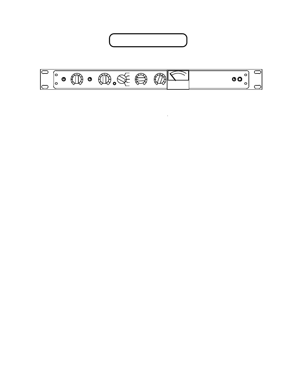
FRONT PANEL
A B C D E F G H I J
A
IN / BYPASS
Switched in bypass mode, (down position) all effects of the limiting circuitry are
bypassed and will not affect the audio signal. In the bypass mode , the audio signal
passes from the input directly to the output.
B.
INPUT
Continuously variable attenuation of input signal entering the amplifier limiting
circuitry. Full attenuation occurs at the fully counterclockwise position.
This control is active only in IN mode.
C.
COMP. / LIMIT
Selects compression ( 1.5:1) or limiting (3:1) function.
D.
THRESHOLD
Continuously variable gain reduction threshold control.
Determines the necessary amplitude for compression or limiting to take effect. Most
extreme effect is at the MIN (fully counter clockwise) position. The lower the
threshold, the more that gets limited.
E.
METER
Factory calibrated. Adjusts zero indication on meter.
F.
RECOVERY
Recovery times can be selected between
a.
VERY SLOW
8 seconds
b.
SLOW
4 seconds
c.
MEDIUM
.6 seconds
d.
FAST
.4 second
e.
VERY FAST
.2 second
G.
ATTACK
Continuously variable sensitivity of transient detection. Determines the necessary
length of transient to initiate gain reduction. Fast =25mS, Med =50mS, Slow =70mS.
Fully counter clockwise at the slowest setting will prevent most percussive signals
from causing limiting or compression.
H.
OUTPUT ATTENUATE
Continuously variable attenuation of output signal leaving the amplifier circuitry.
Full attenuation occurs at the full counterclockwise position.
This control is active only in IN mode.
J.
GR METER
Measures in decibels amount of reduction
K.
POWER ON/OFF
Power is supplied to the unit when switched UP. LED will illuminate